Its now 2015, and the DAC continue to work. CD/DVD/LD players died, came and go, the same DAC continues.
The original circuit diagram provided by the seller for this kit is for DIR9001 interface. For WM8805, you can refer to the spec sheet for block diagram, pin information, setting.
Here is one example:
http://bbs.audio-gd.com/UploadFile/2012-7/20127111157369610.jpg
Pin 16 D out
Pin 18 BCLK
Pin 19 LRCLK
Pin 20 MCLK
The DAC works poorly on Coaxial input with lower end CD players. The DAC works well on Toslink. I found that the actual circuit lacks the 74HCU04 hex invert signal conditioning circuit. The incoming SPDIF signals are fed directly to WM8805 via the on chip selection.
The upgrade done after a few years:
1. Upgraded the input SPDIF using 75ohm/0.1uf RC coupling and 74HCU04 standard circuit. (Excellent result)
2. Upgraded the input SPDIF portion with pulse transformer using 74HCU04 standard circuit.
3. Toslink still an option but not used. USB still an option but not used.
4. upgraded master clock with a stable 12Mhz circuit
5. Replaced the fast recovery diodes with fast 3A diodes -
6. Power supply caps on Analog upgraded to 10000uf 50v
7. Output cap bypassed with 2.2uf and 0.1uf Solen
Will post pictures later.")
The original circuit diagram provided by the seller for this kit is for DIR9001 interface. For WM8805, you can refer to the spec sheet for block diagram, pin information, setting.
Here is one example:
http://bbs.audio-gd.com/UploadFile/2012-7/20127111157369610.jpg
Pin 16 D out
Pin 18 BCLK
Pin 19 LRCLK
Pin 20 MCLK
The DAC works poorly on Coaxial input with lower end CD players. The DAC works well on Toslink. I found that the actual circuit lacks the 74HCU04 hex invert signal conditioning circuit. The incoming SPDIF signals are fed directly to WM8805 via the on chip selection.
The upgrade done after a few years:
1. Upgraded the input SPDIF using 75ohm/0.1uf RC coupling and 74HCU04 standard circuit. (Excellent result)
2. Upgraded the input SPDIF portion with pulse transformer using 74HCU04 standard circuit.
3. Toslink still an option but not used. USB still an option but not used.
4. upgraded master clock with a stable 12Mhz circuit
5. Replaced the fast recovery diodes with fast 3A diodes -
6. Power supply caps on Analog upgraded to 10000uf 50v
7. Output cap bypassed with 2.2uf and 0.1uf Solen
Will post pictures later.
Its now 2015, and the DAC continue to work. CD/DVD/LD players died, came and go, the same DAC continues.
The original circuit diagram provided by the seller for this kit is for DIR9001 interface. For WM8805, you can refer to the spec sheet for block diagram, pin information, setting.
Here is one example:
http://bbs.audio-gd.com/UploadFile/2012-7/20127111157369610.jpg
Pin 16 D out
Pin 18 BCLK
Pin 19 LRCLK
Pin 20 MCLK
The DAC works poorly on Coaxial input with lower end CD players. The DAC works well on Toslink. I found that the actual circuit lacks the 74HCU04 hex invert signal conditioning circuit. The incoming SPDIF signals are fed directly to WM8805 via the on chip selection.
The upgrade done after a few years:
1. Upgraded the input SPDIF using 75ohm/0.1uf RC coupling and 74HCU04 standard circuit. (Excellent result)
2. Upgraded the input SPDIF portion with pulse transformer using 74HCU04 standard circuit.
3. Toslink still an option but not used. USB still an option but not used.
4. upgraded master clock with a stable 12Mhz circuit
5. Replaced the fast recovery diodes with fast 3A diodes -
6. Power supply caps on Analog upgraded to 10000uf 50v
7. Output cap bypassed with 2.2uf and 0.1uf Solen
Will post pictures later.
Hi,
I'm rather new to building digital audio from scratch. In the process of building a modular DAC with swappable boards.
I bought the WM8805 as a complement to the two versions of DIR9001 boards I have built.
I also have one CS8416.
D/A chips are:
WM8740 (one built, one on the way to try them in mono)
PCM1794 (on the way)
TDA1541A
TDA1387 (on the way)
And I have built/am building several versions of filter/buffer.
Of course I'll build a few versions of I/V board for the Iout D/A's.
My question is, since I have a 74HC04 IC, what is the standard circuit for using this as an input?
For the DIR9001 boards I used a 75R resistor(parallel) followed by a pulse transformer PE-65612 followed by SN75176BP.
Hi there,
Welcome to DAC fun.
If you look at Wolfson application circuit page 1, the RX0 and RX1 pins only specify a simple RC (75 ohms, 100n) input circuit. This is insufficient because of the limitations of many poorly executed SPDIF output (Coaxial or Toslink) on many CD or DVD players.
The Ebay DAC kit has a poor SPDIF input circuit. As a result, the Toslink works ok, but Coaxial has a lot of synchronization problem (loss sync, disruptions, etc).
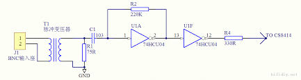
Attached is a typical circuit you can adopt. The parts need not be high end parts, and off the shelf parts should suffice.
The isolation transformer can be from the DAC board or old CD player.
I found that eliminating TX (T1) completely at SPDIF input still works. It has no significant change in sound quality although there is no more ground isolation. On the DAC side there is already D and A ground isolation.
R2 can be 20k or 220k. R4 is optional.
Incidentally, I managed to have this circuit work perfectly using 74HCT04 without the unbuffered version.
Welcome to DAC fun.
If you look at Wolfson application circuit page 1, the RX0 and RX1 pins only specify a simple RC (75 ohms, 100n) input circuit. This is insufficient because of the limitations of many poorly executed SPDIF output (Coaxial or Toslink) on many CD or DVD players.
The Ebay DAC kit has a poor SPDIF input circuit. As a result, the Toslink works ok, but Coaxial has a lot of synchronization problem (loss sync, disruptions, etc).
Attached is a typical circuit you can adopt. The parts need not be high end parts, and off the shelf parts should suffice.
The isolation transformer can be from the DAC board or old CD player.
I found that eliminating TX (T1) completely at SPDIF input still works. It has no significant change in sound quality although there is no more ground isolation. On the DAC side there is already D and A ground isolation.
R2 can be 20k or 220k. R4 is optional.
Incidentally, I managed to have this circuit work perfectly using 74HCT04 without the unbuffered version.
Last edited:
ThanksHi there,
Welcome to DAC fun.
If you look at Wolfson application circuit page 1, the RX0 and RX1 pins only specify a simple RC (75 ohms, 100n) input circuit. This is insufficient because of the limitations of many poorly executed SPDIF output (Coaxial or Toslink) on many CD or DVD players.
The Ebay DAC kit has a poor SPDIF input circuit. As a result, the Toslink works ok, but Coaxial has a lot of synchronization problem (loss sync, disruptions, etc).
Attached is a typical circuit you can adopt. The parts need not be high end parts, and off the shelf parts should suffice.
The isolation transformer can be from the DAC board or old CD player.
I found that eliminating TX (T1) completely at SPDIF input still works. It has no significant change in sound quality although there is no more ground isolation. On the DAC side there is already D and A ground isolation.
R2 can be 20k or 220k. R4 is optional.
Incidentally, I managed to have this circuit work perfectly using 74HCT04 without the unbuffered version.
I have the 74HC04N, PE-65612, resistors mentioned at home.
One more thing, the (2pin 24.576Mhz) crystal I'll use for the AD1896A, Can I connect it: 3.3Vdc LDO -> Crystal -> pin2 (IIRC, don't have the schematic in front of me)?


Hi,
I got my schematics(most of them) from this site:
Audio design guide
Since I already have the 2pin 24.5760Mhz HC-49S crystal oscillator (2pcs),
and I'll put the one I use in a socket(they do age)...I was wondering if I could use that crystal to clock in.
Either as shown in the schematic in the link above or between MCLK_I and MCLK_O with one 12pF capacitor to GND on each side.
The AD1896A board will be set as ASRC to up-/down-sample all source material to 24bit 96Khz. 90% of the time I listen to 44.1Khz material anyway.
So, I want:
I2S
24Bit
256fs (gives 96Khz with 24.5760Mhz)
I guess I should set it like this?
SMODE_I
2: L
1: L
0: H
I2S
SMODE_O
1: L
0: H
I2S
WLENGHT_O
1: L
0: L
24bit
MMODE_O
2: L
1: H
0: H
256fs Output serial port is Master
Or am I misunderstanding something, missing something?
Hi,
From application sheet:
MCLK_I pin can be 5 V input tolerant just like any of the other AD1896 input pins. A fundamental mode crystal can be inserted between MCLK_I and MCLK_O for master clock frequency generation up to 27 MHz. For master clock frequency generation with a crystal beyond 27 MHz, it is recommended that the user use a third overtone crystal and to add an LC filter at the output of MCLK_O to filter out the fundamental, do not notch filter the fundamental. Please refer to your quartz crystal supplier ...
It is good to study the application note of AD1896A before execution:
http://www.analog.com/media/en/technical-documentation/data-sheets/AD1896.pdf
The serial data input port mode is clearly listed on 22 of 28 of the pdf file.
I am sorry I don't toy with asynchronous sample rate conversion.... I can't comment too much.
You can try using 15-22pF caps to ground; and parallel a 1M resistor across the two pins.
This is a pretty standard circuit used on many chips. Good luck
Across? I've seen schematics with a resistor in series with the oscillator(TCXO in that case).
So something like:
oscillator across MCLK in and out, resistor parallel to the oscillator(?) and then one cap on each side to gnd.
Hi, some basic understanding of the oscillator is needed.
This is a Crystal-controlled oscillator (parallel). Inside the chip there is an inverter as amplifier. The inverter gate is effectively a very high-gain amplifier, so its output is a square wave rather than a sine wave. This generates a pulse train and serves as a stable clock.
The 2 capacitors, form a tapped capacitor to the ground. This allows the crystal to provide 180° phase shift required between output and input. The 1M resistor causes the inverter to bias itself at half the supply voltage. Therefore both transistors in the gate are turned on and operating in their linear regions. This value is not critical, 1M to 2M will work.
I have built such an oscillator circuit before to feed the CD player 16.9344M. However, such a circuit has glitches.
Many 3rd party clocks offered commercially uses TXCO with wave shaper, and a very clean and stable low noise power supply (dedicated LM317T with a lot of bypass caps). Currently, for this DAC, I use a 12Mhz TXCO feeding a 74HCT14 schmitt trigger; powered by a dedicated LM317T +5v. It works fine as a simple circuit. You can try TXCO later.

- Status
- This old topic is closed. If you want to reopen this topic, contact a moderator using the "Report Post" button.
- Home
- Source & Line
- Digital Line Level
- Wolfson WM8805 I2S to TDA1541A NOS