yep, there is one spare, because I had actually changed it to 6 from 7 as there was a cancellation, but conrad have supplied me with it, guess they missed the email altering the order. i'll need to go back and check exactly what it costs. shipping to the US right? shoot me an email at qusp (at) optusnet (spot) com (spot) au and we'll work it out from there
Owen,
About the transformer: do you think I can use the antek you recommended with 100 V of main voltage ?
I live in Japan now, but I will move to Europe in one year or so. If I need to have transformers 100-115-230 I have to make a custom order, and it's expensive.
I also found some 50 V secondary R-core, but maybe it's too high.
Thanks,
D.
Any input on this ?
Hi Davide,
I would say that you'll be fine running everything on 100VAC mains. Worst case, you'll need to drop your rails down a few volts to give the regs enough headroom, but going from 45VDC to 40VDC would not likely be audible.
Even if it is a little worse, it's only for a year, so I wouldn't worry about it if I were you.
Cheers,
Owen
I would like to order the dac from Acko .
I can afford the AKD 12 and the AKC 12 to get me started . I already have I/V kit from Owen ..... What else will I need to budget for .....
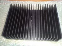
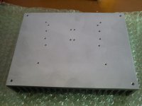
heat sinks I have . PSU can wait till I have built and tested the above .
Advice please Gents ...?
regards ,Rich
I can afford the AKD 12 and the AKC 12 to get me started . I already have I/V kit from Owen ..... What else will I need to budget for .....
heat sinks I have . PSU can wait till I have built and tested the above .
Advice please Gents ...?
regards ,Rich
hi guys, thought i would post this here and will possibly follow up with an update via email. well i have just completed the rather tedious task of matching 100 mosfets for vds, made even more tedious because as i bought in pretty large amount from the same supplier, they are very tightly matched in each rail, with a small difference between each rail. i mean im talking measuring 20 devices in a sitting and getting the whole group within 3mv sometimes with nearly 10 in a row the same, great for the result, but omg i was going barmy last night, i just want this to be over so i can listen to my rig, tempted to find a quad for me first now ") but want the best one for me and it will be better out of more hehe.
but want the best one for me and it will be better out of more hehe.
anyway i'm going to keep going as i've got up a head of steam and will probably just stop at about 140, as looking at the numbers i cant see me needing all 170. then i'll move onto matching for transconductance, now i'm in a rhythm and have a bit of time on my hands it shouldnt take me long to have it all ready for you guys, then i'll start packaging them up, will see how many perfect quads i get and will maybe have a couple of different prices. once i've done a few for transconductance i'll have all the info i need to decide on a price.
anyway thats all, will be back with good news
but want the best one for me and it will be better out of more hehe.anyway i'm going to keep going as i've got up a head of steam and will probably just stop at about 140, as looking at the numbers i cant see me needing all 170. then i'll move onto matching for transconductance, now i'm in a rhythm and have a bit of time on my hands it shouldnt take me long to have it all ready for you guys, then i'll start packaging them up, will see how many perfect quads i get and will maybe have a couple of different prices. once i've done a few for transconductance i'll have all the info i need to decide on a price.
anyway thats all, will be back with good news
no problem, sorry for the length of wait, but as you guys know there has been a fair bit going on over here on the home front, plus the busiest my business has been for some time. i also had a couple problems i had to iron out with the power supply for the matching so i didnt keep blowing regulators when unloaded. basically had to use a different supply and new lower voltage transformer suited to the lower dropout of the regs compared to the supply i'm using for my build.
but i have been going pretty well this last week, getting a rail done each day the last 2 days. for vds not gM, i will do the all for gM starting tomorrow and though i have another bunch of work starting next week, i have some time till then while i wait for parts to arrive; so hope to make good inroads at the very least into the transconductance matching.
but i have been going pretty well this last week, getting a rail done each day the last 2 days. for vds not gM, i will do the all for gM starting tomorrow and though i have another bunch of work starting next week, i have some time till then while i wait for parts to arrive; so hope to make good inroads at the very least into the transconductance matching.
yes, its ongoing, i have continuously had to keep on adding to the test rig for the tc matching part, vds matching was done ages ago. after building up the amp for the sinewave generator i bought a new meter, found ac mv accuracy wasnt good enough for this in the low mVrms, bought an old HP voltmeter, didnt come with the right leads, bought the right parts to make the leads, found buried in the manual that measuring AC vrms with a DC component means that i can only use vrms at its fullscale (300v) resolution instead of its fullscale at 1mv resolution, due to amplified DC transients possibly destroying the input stage.....screamed.
read further and figured i could use the dc output on the back with one of my other meters in conjunction with building yet another accurate and low noise mono instrumentation amplifier to amplify the output gain to a known high level so accuracy of my fluke is increased and the voltage at the back (fullscale -1vdc deflection) x 10 (or perhaps 100) and measured, then divided by 10 (or perhaps 100) will give very good results.
i've had to work all of this in with work and work through and build the whole thing by myself, because I still have not heard from opc at all, except to say that he had been very busy and would reply the next day, that was about 3-4 weeks ago and about a month before that to say roughly the same thing although i have seen the odd post in 'the wire' thread, which is last place i had contact
i'm a patient man Owen, but man, whats up where are you? its been good working through these roadblocks myself and i realy do know you are busy also and this is out of your free time, just as with myself, but pretty sure you would have been able to warn me of at least some of them.
so anyway again i'm back on track, as i finished the amp for the back of the meter yesterday, so will find some time tonight, or in the morning to set up the rig again and get moving. believe me, noone is as frustrated with the length of time its taking as i am, no way will i get that time back.
Last edited:
hey hey guys, well i have some good news, i gave you the saga already, found that i needed to research, design and build a circuit that i could attach to the gate and source points and tap the AC voltage there while injecting a 3vrms 1khz sine wave. i needed to be able to do this with accuracy and without effecting the matching cct by loading it down and then multiply this to gain greater accuracy and at the same time subtract one from the other, emulating what a meter does when you measure across 2 points. i couldnt do this with the hp, because the circuit points are well above ground. so the solution was to build something that did not effect the testing cct, while allowing me to connect the hp and take the dc voltage out of the equation, while increasing accuracy.
anyway i've finished building and just tested the differential instrumentation amp with 100x gain and i'm very happy with the results, i will attach to the matching circuit tonight or tomorrow and i'm off to the races. at the moment my testing shows that i can use this in combination with the hp to measure the voltage in millivolts from gate to source with around 0.001% accuracy and thats in absolute terms, relative matching should be the same or better. so provided i havent missed something obvious and it works just as well in situ, i'll get right on with it, finally with everything i need. i made it pretty overkill, after the trouble ive had getting the tools to work as designed, when i had something i controlled the design for i had to make sure.
here is the thread i started to make sure i was on the right track before building it.
Last edited:
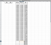
your telling me, built and tested the above diff amp without the matching cct and was perfect, attached to the cct and even with the caps inline there was still enough leakage of dc to clip the 2nd stage with dc once the gain was added  tried another isolation transformer and it loaded the cct, no good and finally tried another set of film caps in between the input buffer and the summing amp and success!! no DC finally i could get on with it. that was last night, woke up today, sorted out some work first and i've knocked off a rail of them since about 6pm. best doing them at night due to fairly constant temperature. wont be able to do a rail each evening, that was a good 8 hours. each is bolted into place and after about 60seconds its up to the right voltages, adjust if needed and when settled start a 3 minute countdown timer. at the end of the 3 minutes i take the reading for each one... rinse..... repeat
the above is the gm, all vds is done. the middle row is the measurement that has been causing the grief, now it actually contains another 2 decimal places to the right that are cutoff. they are taken into account for the calculation on the right, but it rounds off for display
tried another isolation transformer and it loaded the cct, no good and finally tried another set of film caps in between the input buffer and the summing amp and success!! no DC finally i could get on with it. that was last night, woke up today, sorted out some work first and i've knocked off a rail of them since about 6pm. best doing them at night due to fairly constant temperature. wont be able to do a rail each evening, that was a good 8 hours. each is bolted into place and after about 60seconds its up to the right voltages, adjust if needed and when settled start a 3 minute countdown timer. at the end of the 3 minutes i take the reading for each one... rinse..... repeatthe above is the gm, all vds is done. the middle row is the measurement that has been causing the grief, now it actually contains another 2 decimal places to the right that are cutoff. they are taken into account for the calculation on the right, but it rounds off for display
Attachments
Last edited:
- Home
- Source & Line
- Digital Line Level
- Build Thread - A New Take on the Classic Pass Labs D1 with an ESS Dac