Hi Merlin,
Looks great! I'm glad to see some solid build progress.
It's not so much a weight thing as it is a surface area thing. Extra mass will give you a longer thermal time constant, but since this is a class A design, a large thermal mass won't get you anything - unless you only plan in running it 20 minutes at a time.
There are several online calculators for figuring out what the delta-t will be based on power put in, surface area of the sink, and air flow rate.
If you can post a side profile with measurements so an accurate surface are can be calculated, then we might be able to give you a better idea of how large the sink will need to be. Giving you an answer based on weight would be incorrect.
Cheers,
Owen
Salomon,
Sorry for not replying sooner, I forgot about your post.
Excellent work on the board, everything looks really good! I was expecting at least a few people would have this up and running by now, but it has been a busy couple of weeks with the holidays.
I'm looking forward to your impressions, so let us all know when you get it up and working.
Cheers,
Owen
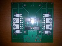
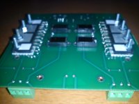
I was planning to solder these component to the PCB only after mounting them firmly on the heat sink. Just to avoid stress/tension on the joints in case of minor placement imprecisions. But maybe I got the best strategy wrong.Waiting the heat sink weight to cut, a photo with all resistors & mosfets just for fun
Cheers,
Nic
I was planning to solder these component to the PCB only after mounting them firmly on the heat sink. Just to avoid stress/tension on the joints in case of minor placement imprecisions. But maybe I got the best strategy wrong.
Cheers,
Nic
I soldered with the screws & nuts firmly so I don't see any reason to have stress/tension on the joints: I am waiting the qusp heat sink are properly drilled

Cheers,
Felipe
I'm sorry, but I don't understand: onto what did you fix the components prior to soldering?I soldered with the screws & nuts firmly so I don't see any reason to have stress/tension on the joints: I am waiting the qusp heat sink are properly drilled
Cheers,
Felipe
I'm sorry, but I don't understand: onto what did you fix the components prior to soldering?
Onto the pcb, see post 101
")
yeah I was going to attach the devices to the sink and then solder as well, but with the layout the way it is, its not as critical as normal and if you have used pieces of PCB to make sure the level is the same for all, then there should be no problem.
opc: yeah I expected more people to have finished by now (or at least 1) I mean many are waiting on fets or something from me, but nowhere near all.
the heatsinks are finished, I will have them this week sometime I hope, but still need to get the matching done, so thats where i'm at for the next while.
merlin: the info you have posted so far is still not what is needed, the volume/weight are pretty much meaningless for dissipation, only how long it takes to heat up. the manufacturer should have listed a rating for 0.XX degrees C/W @ a specified temp, often 80c
as opc said, its surface area that is meaningful for dissipation, but dissipation should be listed as a spec
Last edited:
qsup
I don't have the manufacturer heatsink spec, my heat sink is from an old Musical Fidelity MA 65 mono power amp, so can't use it?
Yes I have used pieces of PCB to have the same level for all resistors & mosfets, see attached photo.
Good news about heatsinks, please let me know when you send me.
I don't have the manufacturer heatsink spec, my heat sink is from an old Musical Fidelity MA 65 mono power amp, so can't use it?
Yes I have used pieces of PCB to have the same level for all resistors & mosfets, see attached photo.
Good news about heatsinks, please let me know when you send me.
Attachments
I still have no idea of whether its up to the task, without the relevant info nobody can, the IV dissipation of 2 channels is over 40W without the regs, what was the power of the amp?
at this stage you have more info than we do and you can just use some other circuit that puts out a known amount of heat/power and measure the temp of the sink to see if it will cope with the D1
I will not be sending the sink until the fets are ready, unless you want to pay 2 lots of shipping. (or am I confused, I thought you were getting matched fets too?) I was told they would be doing everything to get them done last week before new years, but I guess they didnt get them done, because I got news today that they will be ready this friday, as in tomorrow (its 1.30am thursday here)
Last edited:
So, I started assembling the board. I started with the caps that are a bit bigger than the rest. I am not sure I am getting the desired results. How do I know if I have a cold soldering ? I mostly have problem when I have to solder components that are connected to the ground plane. Do you put the soldering iron on the component or on the board to melt the tin ?
Thanks,
Davide
Thanks,
Davide
So, I started assembling the board. I started with the caps that are a bit bigger than the rest. I am not sure I am getting the desired results. How do I know if I have a cold soldering ? I mostly have problem when I have to solder components that are connected to the ground plane. Do you put the soldering iron on the component or on the board to melt the tin ?
Thanks,
Davide
Wow... usually you should start with the "lowest" components first...
As for component leads to the ground plane, make sure you raise the solder iron temp higher and heat the ground plane surrounding first (and longer).
The result should be a "smooth surface" shinning solder point that indicate is not a cold soldering point... you can google solder tips and found a lot video to help you.
yes, Davide, stop with the large caps you should start with the smallest SMD parts first and work your way up. I normally solder the ground side of all the components first with high heat and high mass tip and then change tips to a lower mass tip. do not heat the lead, heat the pad and junction of the lead and flow the solder onto the pad.
Iloveswan, you are correct that in most cases a shiny smooth joint is an indication of a good joint, but if the lead is moved while part way through it can cause an invisible fracture and also lead free solder does not produce a shiny joint no matter how well done it is.
Merlin, OK I wasnt looking at your records when I posted and had wondered if you hadnt ordered fets as you had soldered some there. I dont have them yet, I will send them the first chance I get after I receive them, hopefully this coming week. they are not being sent to me express, as its a large package and would cost heaps to do that. even sending registered mail is pricey for something this size and weight. all the same if they are sent on monday I should get them before the end of the week. they should have been ready today, anyway enough talk of these heatsinks in the build thread.
Merlin, please have some patience and read my posts, it is starting to frustrate me I have been forthcoming with information about the progress in my posts at every point, if they were only finished today, how could I have them already and send to you? they are in Australia, but are thousands of km away.
Iloveswan, you are correct that in most cases a shiny smooth joint is an indication of a good joint, but if the lead is moved while part way through it can cause an invisible fracture and also lead free solder does not produce a shiny joint no matter how well done it is.
Merlin, OK I wasnt looking at your records when I posted and had wondered if you hadnt ordered fets as you had soldered some there. I dont have them yet, I will send them the first chance I get after I receive them, hopefully this coming week. they are not being sent to me express, as its a large package and would cost heaps to do that. even sending registered mail is pricey for something this size and weight. all the same if they are sent on monday I should get them before the end of the week. they should have been ready today, anyway enough talk of these heatsinks in the build thread.
qusp said:because I got news today that they will be ready this friday, as in tomorrow (its 1.30am thursday here)
Merlin, please have some patience and read my posts, it is starting to frustrate me
I have been forthcoming with information about the progress in my posts at every point, if they were only finished today, how could I have them already and send to you? they are in Australia, but are thousands of km away.
Last edited:
also as both myself and opc said earlier in the thread, you can tin the pad first (ground side) and then heat the pad and slide the part into position, then do the other side, then reflow the ground side. but I will do all of one side and then all of the other. only apply solder to one pad first though, not both; otherwise the part wont sit flat
So I am going on slowly. The solder do not look beautiful, but should be functional. The practical problem I have is that the components got stick to the soldering iron, so I have always to hold it. But if I am holding the component with one hand, and the soldering iron with the other I do not know how to add tin or flux.
Additionally, there is not muck space to put the soldering iron on the board when the component is in place. This makes difficult to me to put heat on the board.
Moreover I realized that I do not have the firmest hand in the world
Sorry if this sound silly, but sometimes in this hobby is easier to overcome theoretical problem, that practical one.
Best Regards,
Davide
the instruction I gave should solve your problems, you do indeed always hold in place with tweezers for the first joint, thus tinning the ground pad first with nothing there, then add some flux to the pad and I will sometimes add some to the component (I use paste) flow that tin and slide the component into place and hold there till solder cools, then solder the other side (you do not need to use the tweezers for this side so have 2 hands) yes some of the pads are only just big enough, but they are big enough, so if the pad is fluxed a decent amount of heat will form a good joint
- Home
- Source & Line
- Digital Line Level
- Build Thread - A New Take on the Classic Pass Labs D1 with an ESS Dac