on top of the above there will be the local shipping to me. some of you have already sorted me for the return shipping of everything to you and a contribution towards the local shipping, but the tapping was not taken into account as the amount was not known, I wish there were more of us getting them though, as it is with only 5 the setup fee and stencil works out to almost half the price, but that is a set fee, so if there were more of us the price would go down a fair bit
I would recommend you do fit the zeners, I have. they are not in the signal until there is a problem. they are to protect the buffalo in case of a fail condition, in a fail condition without these the dac will see all the DC offset, the offset if quite large and would likely kill the dac
I would recommend you do fit the zeners, I have. they are not in the signal until there is a problem. they are to protect the buffalo in case of a fail condition, in a fail condition without these the dac will see all the DC offset, the offset if quite large and would likely kill the dac
Last edited:
Hi Guys,
It's good to see some movement on the construction!
merlin el mago:
You certainly could use those transformers if you have the space for them. There won't be any downside except more dissipation on the regs, and a larger magnetic field, which should be fine if you keep them away from the inputs and outputs. You will absolutely need 100V electrolytic caps on the inputs though as the DC voltage will be close to or over 63VDC.
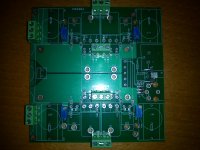
The little SMD parts are indeed the protection diodes for the output of the Buffalo. If you look closely at qusp's pictures, you'll see the little tipis with those zeners. The reason I didn't solder them is that they never would have survived the shipping, and would likely have torn off the pads making it impossible for you to mount them. As qusp suggests, I would mount them if possible, but it's not absolutely necessary. As long as you carefully adjust your circuit prior to tossing on the Buffalo, you should be fine.
qusp:
Looks like a nice collection of goodies you've got there! I'm also jealous of your heatsink venture. I drilled and tapped all my own holes, and it's a serious PITA doing that. Worst part is, I have to do it all over again when I make the proper chassis!
The boards you made up look excellent, and you're well on your way to getting them done.
Keep posting any progress!
Cheers,
Owen
It's good to see some movement on the construction!
merlin el mago:
You certainly could use those transformers if you have the space for them. There won't be any downside except more dissipation on the regs, and a larger magnetic field, which should be fine if you keep them away from the inputs and outputs. You will absolutely need 100V electrolytic caps on the inputs though as the DC voltage will be close to or over 63VDC.
The little SMD parts are indeed the protection diodes for the output of the Buffalo. If you look closely at qusp's pictures, you'll see the little tipis with those zeners. The reason I didn't solder them is that they never would have survived the shipping, and would likely have torn off the pads making it impossible for you to mount them. As qusp suggests, I would mount them if possible, but it's not absolutely necessary. As long as you carefully adjust your circuit prior to tossing on the Buffalo, you should be fine.
qusp:
Looks like a nice collection of goodies you've got there! I'm also jealous of your heatsink venture. I drilled and tapped all my own holes, and it's a serious PITA doing that. Worst part is, I have to do it all over again when I make the proper chassis!
The boards you made up look excellent, and you're well on your way to getting them done.
Keep posting any progress!
Cheers,
Owen
Hi Guys,
It's good to see some movement on the construction!
merlin el mago:
You certainly could use those transformers if you have the space for them. There won't be any downside except more dissipation on the regs, and a larger magnetic field, which should be fine if you keep them away from the inputs and outputs. You will absolutely need 100V electrolytic caps on the inputs though as the DC voltage will be close to or over 63VDC.
The little SMD parts are indeed the protection diodes for the output of the Buffalo. If you look closely at qusp's pictures, you'll see the little tipis with those zeners. The reason I didn't solder them is that they never would have survived the shipping, and would likely have torn off the pads making it impossible for you to mount them. As qusp suggests, I would mount them if possible, but it's not absolutely necessary. As long as you carefully adjust your circuit prior to tossing on the Buffalo, you should be fine.
QFT
yep, definitely recommended, but not compulsory. as long as you have adjusted the bias pots carefully before stacking the buffalo and are very careful whenever you disconnect and reconnect the dac it will be fine, but really i dont see any reason not to do it. I must admit to googling 'the sound quality of zener diodes' and 'high fidelity protection diodes' or something like that prior to fitting them to see if there was any tweak possible here. haha I know i'm a lost cause...... sick I tell you..sick...
 but in the end decided not to bother, as my logical mind knows that they are effectively not there until there is an issue; so fitted them as supplied
Looks like a nice collection of goodies you've got there!
haha indeed!! I reckon theres about 3.5K sitting on that table haha
I'm also jealous of your heatsink venture. I drilled and tapped all my own holes, and it's a serious PITA doing that. Worst part is, I have to do it all over again when I make the proper chassis!
yep, I think its money well spent, I value my time more than it costs and the result will be better than anything I can accomplish here, the stencil allows them about 0.2mm tolerance at worst.
I will also be getting some brackets for bolting the assembly to in the finished chassis, if the right way up this will be attached to standoffs and machine bolts (stainless) so there is some airflow around the heatsinks, or upsidedown only standoffs are needed which are bolted down through the mounting holes on the IV board into matching tapped holes in the heatsink
The boards you made up look excellent, and you're well on your way to getting them done.
yep i've pretty much hit the wall until the sinks get here and fets are matched. still need to get some caps for thorstens power supply and mine, decided rather than using the supply i'm using for my board for matching, that I will use the cut off supply from the board as has 4 separate adjustable outputs, may use 2 of them. I havent fitted the 100k R's on the outputs, as I am using some amtrans carbon comp across the XLRs due to mounting the caps offboard. will probably end up with more Zfoils here.
Keep posting any progress!
will do mate!!
qusp:
Everything is looking fantastic !!!! Your time frame is fine with me. More later.
Best
Bob
thanks for the kind words, yeah its all coming together nicely; glad you are fine with it, kinda sux, but realistically its not going to make any difference to the delivery date.
Last edited:
Hi Guys,
It's good to see some movement on the construction!
merlin el mago:
You certainly could use those transformers if you have the space for them. There won't be any downside except more dissipation on the regs, and a larger magnetic field, which should be fine if you keep them away from the inputs and outputs. You will absolutely need 100V electrolytic caps on the inputs though as the DC voltage will be close to or over 63VDC.
The little SMD parts are indeed the protection diodes for the output of the Buffalo. If you look closely at qusp's pictures, you'll see the little tipis with those zeners. The reason I didn't solder them is that they never would have survived the shipping, and would likely have torn off the pads making it impossible for you to mount them. As qusp suggests, I would mount them if possible, but it's not absolutely necessary. As long as you carefully adjust your circuit prior to tossing on the Buffalo, you should be fine.
Cheers,
Owen
Owen the Tx will be in a separate box, about 100V input caps do you refer to c-38-39-40-41, right wich value for BII?
Hey qusp,
Regarding the heat-sink option with tapped holes from Conrad, is this one large sink with the PCB mounted to the face of it (similar to how opc mounted his board early on for testing)?
yes thats correct, but also with tapped mounting holes at the corners that match the mounting holes on the IV board, so the board and dac assembly is very securely mounted and can be mounted the right way up, or upside-down with brackets or stand-offs. this means that testing is simple and accessible on the bench and then easily moved into a final case. I didnt want to be doing it twice like Owen did. so each device has its own tapped mounting hole, accessed through the holes in the board as well as 4 extra mounting holes at the periphery for mounting to the chassis.
also makes it much easier for people like me who are testing and using several different IV stages, the IV board is not tied to the case so to speak as it has its own sinking arrangements.
Last edited:
this question has been asked several times mate, we recommend leaving them
Sorry possible answered but did not remember, so your advice is not connect nothing, right?
yes thats correct, but also with tapped mounting holes at the corners that match the mounting holes on the IV board, so the board and dac assembly is very securely mounted and can be mounted the right way up, or upside-down with brackets or stand-offs. this means that testing is simple and accessible on the bench and then easily moved into a final case. I didnt want to be doing it twice like Owen did. so each device has its own tapped mounting hole, accessed through the holes in the board as well as 4 extra mounting holes at the periphery for mounting to the chassis.
also makes it much easier for people like me who are testing and using several different IV stages, the IV board is not tied to the case so to speak as it has its own sinking arrangements.
Could I ask one heatsink for me or it's too later?
Hi Guys,
qusp is correct on those capacitors:
Do not populate C32, C33, C38, C39, C40, C41, C46, C47
They form a low pass filter that I don't feel is necessary. Simulations to calculate the proper values are in the other thread if you really feel the need to use them.
As for the picture, I'll post one this evening when I get home from work.
Regards,
Owen
Could I ask one heatsink for me or it's too later?
sure mate, not too late, just in time though. shipping wont be cheap as it weighs just under 1kg. shoot me an email at qusp (splat) optusnet (spot) com (trot) au and we'll go from there, you may also be able to send a mail through the forum (not PM) I cant remember if I have that enabled. with you the price goes down again too, its starting to get quite good value, IMO it was already worth it, but now its getting very decent
I like to mix it up a bit as I think the bots are onto this trick
no problem on the caps Q, didnt mean to sound terse, no need to appologize, i'm a grumpy grumpy man
 and yeah this Q must have been asked and answered at least 10 times already so I guess I was short.
So, I'd like to lift my soldering iron on the board today, but this is my first SMD assembly, I hope I will not screw everything up. I have a bunch of dumb question:
1) I understand that all the SMD caps are not polarized, is it correct ?
2) How do I know the polarity of the diodes ? I can measure the part, but I do not know how it should go on the board.
As procedure to solder the component, I plan to do the following:
1) put a drop of flux on the board.
2) place the component.
3) swipe one contact with the soldering iron with a bit of solder on top.
4) Check the position.
5) solder the other half.
Is it correct ? Any smart tip ?
Thanks,
Davide
Hi Davide,
To answer your questions:
1. None of the SMD caps on this board are polarized, so direction doesn't matter. This is not true for all SMD caps though, as some solid polymer caps are indeed polarized SMD.
2. All diodes have a bar on one side, usually a solid line on the top of the package. Unfortunately, it's very hard to see on these diodes, but it's there. You need to look closely under the right light, and you'll see it. Just place them so the bar on the diode is on the same side as the bar indicated on the board.
For soldering, there are several different ways to go, but here's what I do:
1. Before even taking the parts out of the strip, tin one pad on the PCB for each part to be populated. Always tin the pad with the largest thermal mass. For example, if one side of a component is a trace, and the other is a ground plane, always start on the ground plane side.
2. Once you have one PCB pad tinned (with a little bit of solder) grab the part with some tweezers and hold it in position over the tinned pad. Put a little bit of downward pressure on the part.
3. Touch the tinned pad with the iron and press the part firmly onto the pad. Be sure to heat both the pad and the part.
4. Hold the part in place until the solder solidifies, then repeat this for all parts of one type while being careful to observe polarity if required (for diodes usually)
5. Once each part is soldered on one side, flip the board around and solder the other side of each part.
6. At this point I usually go back and touch up each of the first solder joints and add enough solder to make a nice clean joint. I also put a little bit of side pressure with the iron which helps to detect cold solder joints on the second side. If you got sloppy with any of the second joints, the part will come right off the board when you go back to touch up the first joint.
7. Once all the SMD parts are done, I usually use 99% rubbing alcohol and a toothbrush to clean the flux off the board. I then wash it with soap and water, and dry it well with compressed air. This will leave you with a nice clean board and shiny flux-free joints.
I find this works best for me, but like most things, there are many different ways to do it. Keep in mind that the parts are very small and heat up quickly. Don't overdo it with heat!
I hope this helps!
Regards,
Owen
haha our technique is 100% identical, right down to the toothbrush and alcohol, I use cardas noclean flux though, so its a totally cosmetic thing to get rid of the gungy residue.
I must say though, these 1210 patterns seem to me like you are very used to designing for reflow or wave, as there is very little space on either side of the part. still perfectly doable, but you really gotta make sure the part is centered
I must say though, these 1210 patterns seem to me like you are very used to designing for reflow or wave, as there is very little space on either side of the part. still perfectly doable, but you really gotta make sure the part is centered
I tend to work fast and a bit hotter than some, I use 2 settings and 2 different soldering iron tips for these boards. for the ground plane side I use a high mass, but pointy conical tip at about 370-80 degrees C for the ground plane, but a small difference in my technique is after tinning the ground pads, I reflow each pad with a well tinned soldering tip and slide the part into position while doing this, hold for a split second with heat, then remove the iron and hold the part there till it cools. then when all the ground pads are done I change to the standard conical pointy tip and turn down to about 330-340 to flow the other side; then retouch the ground side and continue as owen. I also apply a small dab of cardas organic flux to the 'leads' of each part and pads before placement
- Home
- Source & Line
- Digital Line Level
- Build Thread - A New Take on the Classic Pass Labs D1 with an ESS Dac