The RTs are pretty large. Are you planning to mount them on the underside of the board? I am going to try the smaller REL RTE. I think pretty soon I will order up a new Legato board.
Hi Barrows,
RTE seems like a good idea if space is a concern. I decided to go with the RT since 1) mounting them on the underside shouldn't be a problem and 2) I may not add caps back to C1-C4 so space probably wouldn't be an issue.
I don't know why 0.001uf RT isn't shown in the official catalog, but various vendors like Percy Audio has it in their catalogs.
Last edited:
I...
have the RTEs on order for both sets of filter caps-I really do not want to eliminate the 15 nF filter (but am lowering value to 10 nF) as I do not like the idea of letting a bunch of HF noise through. I am suspecting the RELs will give more transparency than the Wimas... We shall see. Interesting how the LCRs look very similar to the REL RTE!
have the RTEs on order for both sets of filter caps-I really do not want to eliminate the 15 nF filter (but am lowering value to 10 nF) as I do not like the idea of letting a bunch of HF noise through. I am suspecting the RELs will give more transparency than the Wimas... We shall see. Interesting how the LCRs look very similar to the REL RTE!
They did it BECAUSE the RTE gives a SMALLER footprint on the board. Use RT if you want normal connections.
hmm, logically that doesnt seem to make a great deal of sense, because any square is wider across the diagonal than between the edges and stuffed next to each other there would be wasted space, but perhaps there is something i'm missing. i'll order some and see.
I have thought it through, have you? I mentioned nothing about the height, the leads are at the diagonal edge/corner, which is longer than across, but the effect i'm mainly worried about is the fact that you are left with a pointy corner sticking out the front and rear, so this may make installing them in tight places meant for rectangles problematic and would also make PCB layout rather inefficient unless the patterns are offset, as a grid would mean quite a bit of wasted space, on a 2d plane
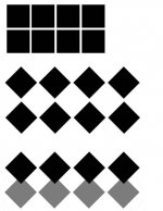
I dont know why it was made, thats my point. this post above was not even directed at you john, but it seems a visual aid is needed. its really pretty straight forward what i'm saying. for starters, a .3" square cap measured across the diagonal is not 0.3" wide but thats not even my point

does this look like an efficient use of space to you? of course if you are able to design your own PCB and dont mind having an offset grid, you can waste only a small amount of space at the edges, but installing them in place of a regular square or rectangular box cap pattern, they wont fit at all unless there has been quite a bit of space wasted on the PCB. the squares above are the same size, in fact the diamond one was a tiny bit smaller. the bottom diagram is the overlap that would be caused if the same vertical spacing was used as the first regular grid, this would also have the same amount of overlap horizontally too, but I couldnt be bothered going that far, it should be easy to see the problem.
like I said mate, i'll still be buying some to try them out, but I just think it was a strange choice, perhaps the performance will make up for it and yeah if you can make your own PCB, or build on perf, its not such a problem.
Attachments
Sorry for thread necroing, but being in the process of rebuilding the linestage of my Buffalo DAC, I could really use some more input.
Please share if you have personal experience with the RTEs, LCR EXFS PS boxes, or Amtrans Polypropelene (or whatever caps that works best). Thank you!")
Please share if you have personal experience with the RTEs, LCR EXFS PS boxes, or Amtrans Polypropelene (or whatever caps that works best). Thank you!
- Status
- This old topic is closed. If you want to reopen this topic, contact a moderator using the "Report Post" button.
- Home
- Source & Line
- Digital Line Level
- Cap choice for analog stage filters?