
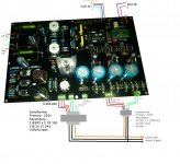
dac board
In pictures attached:
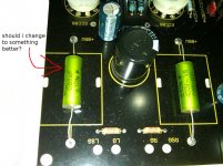
1) 'change' - should i change to something better?
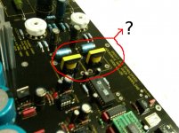
2)'little transformers' - are these transformers? will something better improve the sound?
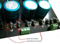
3)'what r these' - what are these little things?
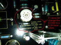
4)'tubes' - what are the alternatives and if I were to change these to some 6.3V tubes, I need to change the jumpers, correct?
Thanks for help.
In pictures attached:
1) 'change' - should i change to something better?
2)'little transformers' - are these transformers? will something better improve the sound?
3)'what r these' - what are these little things?
4)'tubes' - what are the alternatives and if I were to change these to some 6.3V tubes, I need to change the jumpers, correct?
Thanks for help.
Attachments

Hi
I have no experience with this DAC but will try to help.
1) These look good quality output capacitors actually, so you could leave these. But do try some alternatives if you like.
2) These look like output coupling transformers for the I/V stage, and probably good enough. Better ones could be found from Onetics, Jensen or Lundahl but these would be expensive and need to be mounted off board.
3) They are rectifier diodes and look good quality. The missing components are snubber capacitors that would reduce diode noise. Try fitting some if you like to see if they improve sound. Use something like 0.1uF polyester or polypropylene caps.
4) Correct - swap the jumpers for 6.3V. I have no experience with tube output stages but I believe 6DJ8 (ECC88) types are good from Jan Phillips, Tesla etc. Get them matched if you can.
The transformer screen is connected to earth on the inlet, then inlet earth to chassis.
Hope that helps.
You should really read the instruction manual if you were sent one. A few things: Leave those "little transformers" alone. They look more like large inductors to me and must be doing some sort of analogue filtering function.
The ECC88 is a 6.3V tube so the jumpers are in the right position. Stick to the ECC88 until you know what you are doing. I like the sound of the 6N1 but this will consume almost double the heater current of the ECC88. You will have to find out if the heater supply on your board can deliver the higher current needed.
Something missing? No, not really. It is quite common to find spaces for components that have not been inserted on commercial products. This gives the designer options later on. As RichLund points out, these spaces are for small value capacitors called snubbers to kill off noise spikes coming off the rectifiers. Most modern rectifiers do not need snubbers. Adding snubbers may actually make things worse.
Sure you can always change those two output coupling caps. I suggest you get the DAC running first and listen to it before modifying it.
Which part of Malaysia are you from?
- Status
- This old topic is closed. If you want to reopen this topic, contact a moderator using the "Report Post" button.
- Home
- Source & Line
- Digital Line Level
- dac board diagram