Transient DAC two
DAC with Transient modules and DIYINHK 768kHz isolated. Under Transient modules LM317 and LM337 were replaced with TPS7A4700 and TPS7A3301. Isolated part of USB DAC is powered by TPS7A4700 and digital part of Transient modules is powered by LT3045.
DAC with Transient modules and DIYINHK 768kHz isolated. Under Transient modules LM317 and LM337 were replaced with TPS7A4700 and TPS7A3301. Isolated part of USB DAC is powered by TPS7A4700 and digital part of Transient modules is powered by LT3045.
Attachments

This is my favorite dac, LemonDAC.
Wolfson WM8805 receiver, Sabre9023P DAC, Atmega1284p Controller.
Salas pre-regulator, 8 super low noise dc-dc converters (LT3042, TPS7A4700x)
Individual PSU for controller, display and usb receiver.
The engraving of the case has be made on a diy CNC.
Lemon, your DIY project DAC is as attractive and well finished as any commerical DAC I've seen. While reminiscent of Wadia industrial design, I feel that yours is actually better looking. 🙂
Please share the story of it's construction, especially the case design, and the microcontroller firmware development story.
My final destination
My DAC have become a complex of digital channel divider and power amp after several trial and error.
The very reason is analogue interconnection between DAC,channel divider and amp degrades the signal quality most.
Now I connect digitaly from transport with SD card to DAC through optical SPDIF.No analogue cable exists except speaker cable.
Power is from LIFe4PO battery which can be charged by the DAC board.Power amp is classA BTL which gurantees direct current only from the battery.
Power voltage,offset voltage,current and temperature are constantly monitored.In case they are out of order,power goes off instantly.I think protection is very important for power amp.
I'm sure this is the goal.Now is the time for listening not for making.🙂

I forgot to describe DAC chips.When I started self-made,I used pcm1704 and df1706 ,which were the stereotype around 2000.
I redesigned my DAC along with listening room 7 years ago.I made PCB which had pcm1704 and pcm1796 to compare them on the same conditions.
After carefully listening, I decided to choose pcm1704.Bass is more stout than pcm1796. The very reason is I can't examine inside pcm1796 which is a black box. A black box is often fatal for a self-made DAC.From that point,My DAC still uses multibit pcm1704.
I needed to search a replacement for pcm1704 two years ago because pcm1704 became obsolete.There are some multibit precise DACs.I selected LTC2642 among them.FPGA on the board arranges their different pin assignment.
FPGA also has 1st order sigma-delta moduration which can easily improve resolution of LTC2642(16bit) to around 20bit.I think 20bit is practically adequate enough.
I compared them like pcm1704 and pcm1796. Pcm1704 sounded wet like film-based camera,LTC2642 was dry like digital camera. I prefered wet pcm1704 to LTC2642.But LTC2642 were acceptable for a replacement.
That's my history about DAC.My final version can use both pcm1704 and LTC2642.I think LTC2642 can be a replacement for pcm1704.
Liniality of LTC2642 improved by sigma-delta modulation is better than pcm1704K. Pcm1704 is better than LTC2642 below -72dBFS level.
Both have T.H.D around -100dBFS which is inferior to sigma-delta (-120dBFS).I don't care much about T.H.D.Because speakers have much more T.H.D.(at least -40dBFS). -100dBFS is good enough.
Lemon, your DIY project DAC is as attractive and well finished as any commerical DAC I've seen. While reminiscent of Wadia industrial design, I feel that yours is actually better looking. 🙂
Please share the story of it's construction, especially the case design, and the microcontroller firmware development story.
Ken thanks for your positive vote to my dac.
ASAP, I will upload some of the construction tips and what I have done with the software.
Ken thanks for your positive vote to my dac.
ASAP, I will upload some of the construction tips and what I have done with the software.
could you make a thread for that? to keep this thread more general and lean?
Had this out while rearranging the cabinet. It's a BII with NTD1. Originally it was cobbled together piece-meal, but over the last year I finally figured out how to make it into a unit. More aluminum than needed but I keep it in a tight space.
 [/URL][/IMG]
Does it sound terrific as mine? End of the DAC journey for me.
http://www.diyaudio.com/forums/vend...able-bal-bal-se-se-lpuhp-104.html#post5143477
http://www.diyaudio.com/forums/vend...able-bal-bal-se-se-lpuhp-104.html#post5143477
I would imagine that it does. Honestly, it's the only DAC I've ever built but I'm still not left wanting to search for better. There's plenty of other weak links to toy with here. Perhaps a SE Vout DAC for another system if anything. I did see your build btw and thought that it was creative. The open frame approach looks very serviceable. My chassis ending up being about .3degC/w if anyone's curious.
My DAC projects, the big one is PCM1794 based with separate power supplies for the Raspberry, DAC and analog stage.
The small one is a HAT für the Raspberry. More details here:
DIAL-DAC - DIAL audio - DIY
Both DACs running MoodePlayer with Raspberry 2/3.
The small one is a HAT für the Raspberry. More details here:
DIAL-DAC - DIAL audio - DIY
Both DACs running MoodePlayer with Raspberry 2/3.
Attachments


easyDAC
I like DACs powered directly from USB in small case/design.
This my toy is:
- NOS R-2R AD1862 DAC
- line-out direct from I/V
- headphone out based on TPA6120A2 with potentiometer, easily drives all headphones with a lot of power
- no additional filters (only RC) and no caps in series with signal line
- switch between line or headphones (no need unplug something when I choose between headphones or amp), with relays
- for USB/I2S conversion is used PCM2706 (on board are also pins for another I2S), simplicity, no additional drivers, I like Plug&Play and I am listening mostly in 16bits
- power from usb is converted with isolated DC-DC DCP0205xx, regulated to +-5V for digital and AD1862 digital, +-12V for AD1862 analog and I/V, +-5V for TPA6120A2
- it can handle custom I/V boards in small design, +-12V
- 4 layers board
😉
Attachments


Last edited:
Hi Miro1360,
Your DAC is great, sounds good? I also want to make a DAC AD-1862! 🙂
thank you ... definitely, AD1862 are just perfect, so much details, there is no delta-sigma which can beat AD1862, maybe sometimes in future something from ESS, but not yet 😀 .... from R-2R it can be beaten by PCM1704, but they prices are now galactical and fast impossible to find something new ...
do you want build mine configuration or you want own design?
if you decide for my design as is, I can send you PCB for free with all instructions (a lot of parts are SMD, it means you need some soldering skill for SMDs) ... why free - because I left with few PCBs from my build and I am not for commercial here, only what I want back is your honest opinion about sound after your build, because some people forget on this, it is sometimes hard to find honesty ...
if you want own, here are my small hints:
- avoid all digital filters
- if you like power supply from socket, go with small toroid and LM317/337, separate digital and analog, be sure you end up with good ground design ...
- for usb/i2s try jlboard - it is xmos based and it have direct configuration for AD1862 (you dont need additional logic for pcm) ... if you want standard I2S you need additional PCM logic - take it from pavouk.org site from PCM1702 (both are 20bit)
- for I/V, start with active I/V without additional filters, maybe only RC (really, avoid opamp filters), here active I/V .... for I/V you can try LME49990 or others, here are many opamps with good sound result ...
Last edited:
Hi Miro,
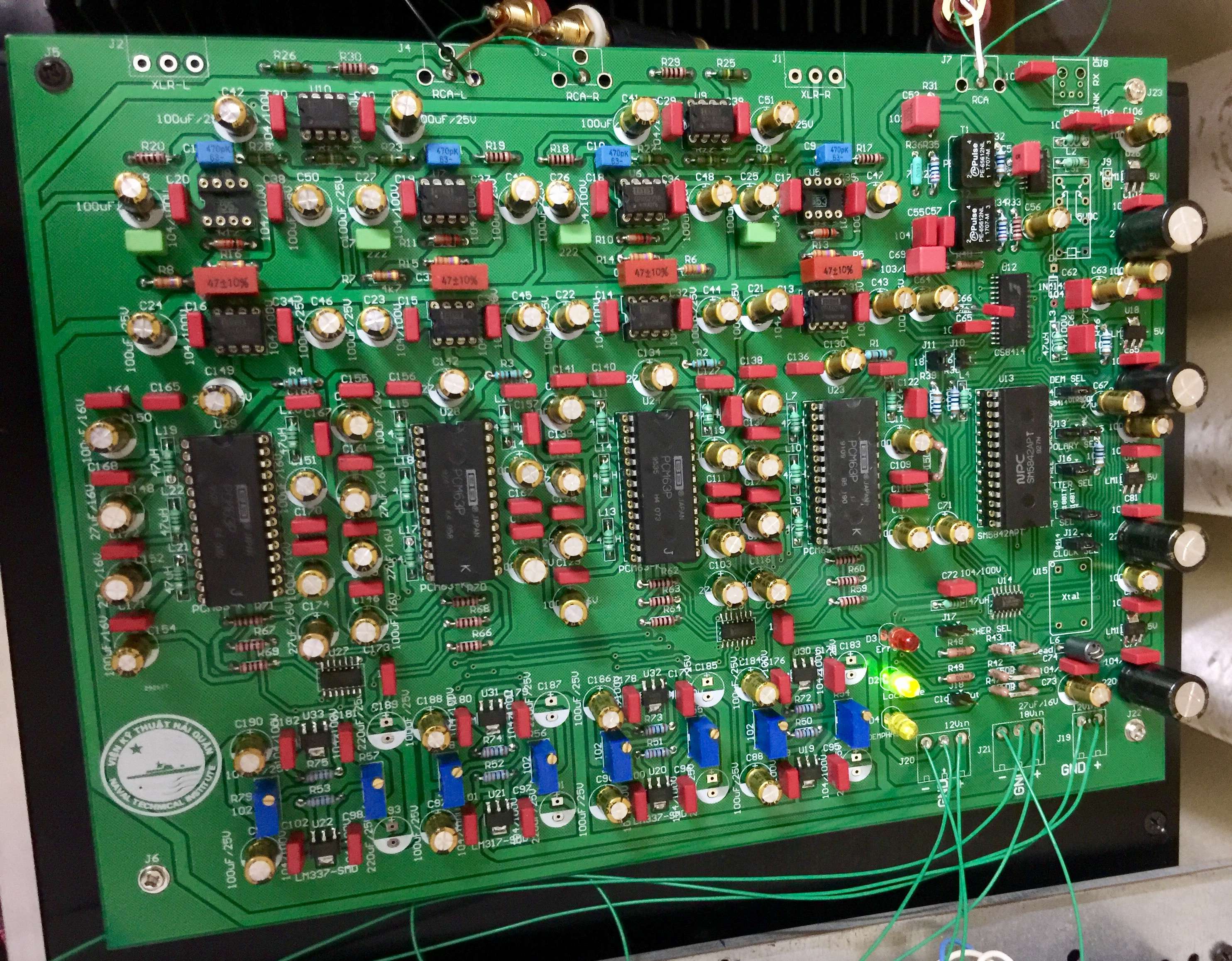
Thank you, i want to build own with Spdif input, USB and Optical. If you can send me your schematic, of course I am not for commercial use but for my own use. After the success I will evaluate the sound quality and feedback let you know. I also have the design for DAC chip PCM63, it is also a chip quality equal to AD1862. If you want I will send the schematic file (Orcad) for your reference.
Thank you, i want to build own with Spdif input, USB and Optical. If you can send me your schematic, of course I am not for commercial use but for my own use. After the success I will evaluate the sound quality and feedback let you know. I also have the design for DAC chip PCM63, it is also a chip quality equal to AD1862. If you want I will send the schematic file (Orcad) for your reference.
Thank you very much for the schematic, i will try and give you feedback on the implementation steps as well as sound quality.
@laxanerde
Nice looking moode players! Can you explain why you have extra wiring to the Pi? I can see the 5v supply but also some extra wires (yellow and orange)
Also, where did you get your psu pcb,s? Did u make these?
Stu
Nice looking moode players! Can you explain why you have extra wiring to the Pi? I can see the 5v supply but also some extra wires (yellow and orange)
Also, where did you get your psu pcb,s? Did u make these?
Stu
Hi Stu,
thanks. The extra wires are for the power switch. I have implemented an additional circuit for save switch off the Pi.
The blue pcbs are selfmade.
thanks. The extra wires are for the power switch. I have implemented an additional circuit for save switch off the Pi.
The blue pcbs are selfmade.
- Home
- Source & Line
- Digital Line Level
- DAC gallery