spdif to i2s decoder question
Hello! I think this site is very useful for beginners
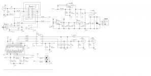
http://www.pavouk.org/hw/modulardac/en_dir9001spdif.html#schematics
Here is dir9001 to I2S decoder.All is good but he used resistors and capacitors to get a clock,i did not like it.Can not we use external 1ppm oscillator?Should we connect oscillator to pin22 ?Does 12MHz oscillator works there?How to calculate the oscillator frequency?Thank you very much
Hello! I think this site is very useful for beginners
http://www.pavouk.org/hw/modulardac/en_dir9001spdif.html#schematics
Here is dir9001 to I2S decoder.All is good but he used resistors and capacitors to get a clock,i did not like it.Can not we use external 1ppm oscillator?Should we connect oscillator to pin22 ?Does 12MHz oscillator works there?How to calculate the oscillator frequency?Thank you very much
He didn't use resistors and capacitors to get a clock, he used the DIR9001's internally generated clock. Seeing as you're a beginner I'd stick with that - even those with lots of digital audio experience hesitate at designing low jitter VCXOs and associated PLLs.
In short, no you can't use an external crystal oscillator as it needs to match the input sample rate. Otherwise you'll get glitches in the output audio - some people don't mind this though.
In short, no you can't use an external crystal oscillator as it needs to match the input sample rate. Otherwise you'll get glitches in the output audio - some people don't mind this though.
Hi.Yes i just remember a bit about PLL from university lab ")
What about this dac
DAC TDA1543*4+WM8805 NOS USB, Optical, Coaxial input | eBay
It seems good but it uses gates as i know.
I think people use 74hc gates because of they parallel many tda1543 chips and they need buffer,but it may make some trouble about sound(more jitter ,delay i think)
Some people write they get more natural sound with a piece of tda1543 maybe because of no need to buffer with gates.I think two designs may have some advantages and disadvantages.
I think i will built a dac with WM8805 with dip converter.In lampizator site he removed the transformer of optical receiver.I will not use transformer after optical receiver.He says he removed a thick blanket when removed the transformer of rx optic...
I will directly send I2s signal to tda1543 not use a gate buffer.I will use ecddesigns dc coupled design.And i will use B1 buffer after dac.So i think it will be very good then.What do you think?There may be many options but i do not want to try all of them.Just want to get most clear sound.Thanks in advance
What about this dac
DAC TDA1543*4+WM8805 NOS USB, Optical, Coaxial input | eBay
Yep, I have one of those. Sounds nice once the grounding is corrected. A bargain at the price.
I think people use 74hc gates because of they parallel many tda1543 chips and they need buffer,but it may make some trouble about sound(more jitter ,delay i think)
I don't recall it using gates - I did add gates in the course of my mods. Sure they add a little jitter but probably not as much as there is already. Jitter in my experience isn't a barrier to getting high end sound.
I think i will built a dac with WM8805 with dip converter.In lampizator site he removed the transformer of optical receiver.I will not use transformer after optical receiver.He says he removed a thick blanket when removed the transformer of rx optic...
WM8805 is a good basis for a design, but really good sound can still be achieved with CS8414 or DIR9001 which I'd recommend for a beginner. I'm listening to a DAC right now with CS8414 - I have no doubt it can be further improved with WM but its really satisfying even now.
I will directly send I2s signal to tda1543 not use a gate buffer.
The advantage of using an HC buffer is mainly to do with keeping the noise levels down. I guess you're not at that stage yet in your modding.
I will use ecddesigns dc coupled design.And i will use B1 buffer after dac.So i think it will be very good then.What do you think?There may be many options but i do not want to try all of them.Just want to get most clear sound.Thanks in advance
I have no experience with those, so no comments to offer here. If you're just starting out then begin with the simplest design - a single TDA1543 and DIR9001 like this one:
High end DAC TDA1543 DIR9001 kit DIY WH-1 | eBay
That board was my starting point for developing beautiful NOS sound.
Does anyone have the schematic for this? I would like to run this dac with two seperate power supplies. I have 3.3v running from an external source (post regulator) to existing 3.3 regulator that powers the digital circuits. I would like to power dacs isolated with the LM317 already onboard.
I think this requires digital grounds to be kept separate on the board. The whole board has a ground plane built in though. :|
I've managed to work out the GND joints around the output side of the dac(s), however the LM317 is an adjustable regulator type, i.e. the ground there is less obvious; there is a few of components dotted around the regulator, which powers only the 43s. I know the 43s have decoupling caps and ground pins themselves and would like to keep the ground at DC jack, dac and output section seperate from the digital section if that makes sense (?)
Any idea best place to contact? (maybe the expert can chime in)
Last edited:
- Status
- This old topic is closed. If you want to reopen this topic, contact a moderator using the "Report Post" button.