Not sure if I'm in the correct part of the Forum, so please move if needed.
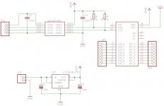
For my Twisted Pear Metronome ASRC I want to build an Arduino based IO expander to control the settings of the SRC4192. Main components will be the i2c isolator ADUM1250 and IO expander PCA9555. I attched an Eagle printout of a possible circuit. As I'm just a diy-er I would be grateful for some input before I order the parts.
Some questions I have:
- does the circuit look ok? Not that I expect you to read the datasheets for me of course (I tried) but perhaps you recognize the components and have some experience with them.
- Can you suggest a better regulator? I need about 210 mA max and don't want to use a smd component and it should be as quiet as the regulator used on the Metronome (LP2985).
- Is it ok to put the ADUM1250 on a browndog adapter?
I have to give credit to diyaudio member GLT for all the info on his blog (H I F I D U I N O). This is where I learned a lot about the Arduino and found the suggestions for the ADUM1250 and PCA9555.
Any help would be great.
Thanks,
Jeroen
Attachments
Hi, thanks for the credit ") . Apple remote huh? you must share the code!
. Apple remote huh? you must share the code!
At first sight, the circuit looks fine (but I have not implemented them myself). Regarding the regulator, you can't find anything with lower noise that is not smd. The lt1963 should be lower noise than that in the Metro.
. Apple remote huh? you must share the code!At first sight, the circuit looks fine (but I have not implemented them myself). Regarding the regulator, you can't find anything with lower noise that is not smd. The lt1963 should be lower noise than that in the Metro.
For the appleremote it was a bit hard to find the codes. From searching the web I sort of learned that it uses the NEC protocol; 9.5ms/4.5ms start pulse and then 4 bytes data. It seems that the third byte is the command and the fourth the appleremote id.
Below is the test code I used. The method is the same as on the HIFIDUINO log but now repeated 4 times to catch all four bytes. The lcd commands are just to show the results.
// get ir key
int getIRKey() {
int duration=1;
int result1=0;
while((duration=pulseIn(IRPIN, HIGH, 100000)) < 4000 && duration!=0)
{
// wait for sequence
}
// get byte 1
int mask = 1;
int test1 = 0;
// get 8 bits
for (int i = 0; i < 8; i++)
{
// get pulse length
duration = pulseIn(IRPIN, HIGH, 1700);
// get 1 and update bit
if (duration > 1400) {
result1 |= mask;
test1++;
}
// shift mask to next bit
mask <<= 1;
}
// get byte 2
int result2=0;
mask = 1;
int test2 = 0;
// get 8 bits
for (int i = 0; i < 8; i++)
{
// get pulse length
duration = pulseIn(IRPIN, HIGH, 1700);
// get 1 and update bit
if (duration > 1400) {
result2 |= mask;
test2++;
}
// shift mask to next bit
mask <<= 1;
}
// get byte 3
int result3=0;
mask = 1;
int test3 = 0;
// get 8 bits
for (int i = 0; i < 8; i++)
{
// get pulse length
duration = pulseIn(IRPIN, HIGH, 1700);
// get 1 and update bit
if (duration > 1400) {
result3 |= mask;
test3++;
}
// shift mask to next bit
mask <<= 1;
}
// get byte 4
int result4=0;
mask = 1;
int test4 = 0;
// get 8 bits
for (int i = 0; i < 8; i++)
{
// get pulse length
duration = pulseIn(IRPIN, HIGH, 1700);
// get 1 and update bit
if (duration > 1400) {
result4 |= mask;
test4++;
}
// shift mask to next bit
mask <<= 1;
}
lcd.clear();
lcd.setCursor(0,0);
lcd.print(result1);
lcd.setCursor(0,10);
lcd.print(test1);
lcd.setCursor(1,0);
lcd.print(result2);
lcd.setCursor(1,10);
lcd.print(test2);
lcd.setCursor(2,0);
lcd.print(result3);
lcd.setCursor(2,10);
lcd.print(test3);
lcd.setCursor(3,0);
lcd.print(result4);
lcd.setCursor(3,10);
lcd.print(test4);
return result3;
}
It works!!
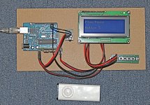
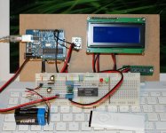
That is, I can control the red and green led with the apple remote... The pic is a bit vague but the lcd says "right" and the green led is on.
Next is to find out how I can control the spdif input selector on the TP CS8416 receiver module before it goes onto print and into the DAC.
Funny toy this Arduino.
Jeroen
Attachments
JeroenR, Nice work.
I've started to look at your code. (because I also want to use an Apple remote). According to the NEC protocol, the encoding is "pulse distance modulation" SB-Projects: IR remote control: NEC protocol
That means that each pulse is 560 usec and you measure the distance between pulses. Your code counts as 1 if duration > 1400, but duration will never be > 1400 according to the NEC protocol. Can you explain further?
Thanks.
Thanks.
Take a look at Apple Remote Arduino shield - Hack a Day
Above link also points too a library, in this case for sending, not receiving. A little quote from the library :
"Notes:
1) Apple's remotes use the NEC IR protocol, which is better
described here: SB-Projects: IR remote control: NEC protocol
It uses a 38 kHz carrier wave ( hence the OscWrite call) and uses a
"pulse distance" encoding. In other words, the LED is ON for the same
amount of time - it is the duration OFF that matters.
The protocol header is a 9ms on, followed by 4.5 ms off. A '1' value is
.560 ms on, followed by 1.690 ms off. A '0' value is the same on pulse,
followed by .565 ms off.
The 'end' header is a .560 ms on pulse.
2) The total data transmitted is 32 bits. "
It is some time ago but as the irpin as always high, should I then not be measuring the "off's" as high's? I'm writing this from work so I'm not too sure.
And... the code is just test code that does work. It could be it works by accident.
Jeroen
Thanks.
It is some time ago but as the irpin as always high, should I then not be measuring the "off's" as high's? I'm writing this from work so I'm not too sure.
And... the code is just test code that does work. It could be it works by accident.
Jeroen
If that is the case, then it will work (after figuring out what to do at the byte boundaries). I'll have review and see how the ir receiver works

My version of the code for the Apple Remote. A refinement from what JeroenR has implemented: H I F I D U I N O
very neat work! I too love the LT1963, I think it is an under used IC here, seems on here people are either allergic to using any ICs at all, or if they do they use something substandard like LM317/337. when sensing is used with the LT1963/LT1175A combo it makes for a pretty fantastic bipolar regulator even better (for lower currents) is there SMD single package bipolar reg the LT3032
- Status
- This old topic is closed. If you want to reopen this topic, contact a moderator using the "Report Post" button.
- Home
- Source & Line
- Digital Line Level
- IO Expander for TP Metronome