Hi,
I'm about to build the lampucera DAC with tube output buffer (as cathode follower)
http://www.lampizator.eu/LAMPIZATOR/LAMPUCERA/MAX/IMG_5143.jpg
I don't need any other sources and I have no need for EQ, so I thought I would skip the preamp and connect the dac directly to my power amp (Quad 303).
As I still need volume control I'm planning to add a tube amp stage with volume control after the cathode follower. The quad has a low input impedance (22kOhms) so I'm not sure which design would be best? My speakers are Quad ESL 57's.
Is this a good idea in general or am I missing something?
Thanks a lot,
Teo
Hi Teo,
looks like the signal level is just right for your power amp. This means that you don't need extra gain.
For volume control, you could suffice with a 5kohms stereo pot at the output of the buffer. Your output coupling cap should then be at least 5uF.
If you will be using *really* long cables to your amplifier, or want to use a smaller coupling cap, you can put a second cathode follower behind the volume pot. The volume pot can then be much larger (100Kohms) and the coupling cap could be 220nF or so. But this requires a second tube.
HTH,
Kenneth
Hey Teo,
First of all, do you take the signal directly from the chip without any buffers in between?
Don´t use the schematic above as is. You will get high distortion due to excessive loading from the small cathode resistors!
Also why is there caps between DAC and CF???? Deleting them would better performance as the cathode-resistors would get higher values. Can redraw if you want to.
Still, using this circuit will degrade DAC-performance due to the added distortion from this mediocre design.
If you have typical voltageDAC, Cirrus etc. only a cap followed by a pot directly from the DAC is needed. No tube!
Personally I doubt it is the best of ideas to only use one of the balanced outputs but it obviously works.
Hey Teo,
First of all, do you take the signal directly from the chip without any buffers in between?
Don´t use the schematic above as is. You will get high distortion due to excessive loading from the small cathode resistors!
Also why is there caps between DAC and CF???? Deleting them would better performance as the cathode-resistors would get higher values. Can redraw if you want to.
Still, using this circuit will degrade DAC-performance due to the added distortion from this mediocre design.
If you have typical voltageDAC, Cirrus etc. only a cap followed by a pot directly from the DAC is needed. No tube!
Personally I doubt it is the best of ideas to only use one of the balanced outputs but it obviously works.
Lars, I completely agree with everything you have said and would take it further wrt to using only one of the balanced outputs: unacceptable..

If this is a balanced output voltage dac I would use a transformer to convert the balanced drive to an unbalanced output - simple, works well and sounds surprisingly good with the right transformer.
Given the gain requirements and the output voltage from the dac a 2:1 stepdown should work well and drive a 5K pot with no problem at all. (I'd look to Lundahl for suitable transformers.)
Well spoken Kevin. Was trying to be a little diplomatic about the balance/unbalanced ting.
And yes, 2:1 seems to be a good idea wrt levels. Except for helping us get unbalanced out when using transformers we also get rid of the 2,5V DC from the chip.
It doesn´t have to be the most expensive LL either. The amorphous 1544A is a great choice among the smaller ones. A good source for Lundahl in Europe is Benny at Aquablue.
.And yes, 2:1 seems to be a good idea wrt levels. Except for helping us get unbalanced out when using transformers we also get rid of the 2,5V DC from the chip.
It doesn´t have to be the most expensive LL either. The amorphous 1544A is a great choice among the smaller ones. A good source for Lundahl in Europe is Benny at Aquablue.
Hi revintage,
thanks for your reply,
Yes, I will be taking the signal directly from the chip.
Isn't there always a cap there in a cathode follower design?
But would I then not be missing a buffer since I want to connect the dac immediately to the amp which is low impedance?
Thanks, I'm still rather new to audio electronics and I appreciate your help!
Regards,
Teo
thanks for your reply,
First of all, do you take the signal directly from the chip without any buffers in between?
Yes, I will be taking the signal directly from the chip.
Also why is there caps between DAC and CF???? Deleting them would better performance as the cathode-resistors would get higher values. Can redraw if you want to.
Isn't there always a cap there in a cathode follower design?
Still, using this circuit will degrade DAC-performance due to the added distortion from this mediocre design.
If you have typical voltageDAC, Cirrus etc. only a cap followed by a pot directly from the DAC is needed. No tube!
But would I then not be missing a buffer since I want to connect the dac immediately to the amp which is low impedance?
Thanks, I'm still rather new to audio electronics and I appreciate your help!
Regards,
Teo
That cathode follower design you posted is 100% garbage - unless you want around 20% distortion.
A cathode follower needs a good amount of voltage (let's say 50V) across it's cathode resistors - this has almost none.
Use a transformer - or just a cap , but TRASH that Cathode follower!
Regards, Allen
A cathode follower needs a good amount of voltage (let's say 50V) across it's cathode resistors - this has almost none.
Use a transformer - or just a cap , but TRASH that Cathode follower!
Regards, Allen
Hi Allen,
thanks for your answer!
Actually the schematic is not mine but from Mr. Fikus at Lukasz Fikus Lampizator. He seems to use it quite successfully in many of his projects.
But I don't want to question you guys, because as I said, I'm a complete newbie.
I'm just worried that with just a cap after the DAC I would not have any output buffer before my amp.
Hey Teo,
Mr. Fikus might be a man with a lot of enthusiasm about CD but the schematics from him shows that he haven´t any skills to design acceptable tube-circuits. As Allen says this one is 100% garbage. Forget it!
You might get away with it using a 6H30 with an Ug of 7V/10mA and a single BJT CCS, still not what I would recommend.
The DAC you have has just a few ohms Zout. Adding a 5k pot gives you a worst case Zout of 1,25k so there will be no problems whatsoever to drive your QUAD. No need for a buffer unless you use extremely long and high capacitance cables. The output cap must be choosen for 5k which gives you 6,8u for -3dB at 5Hz.
You still have the problem with taking the signal from only one side which is should be a No-No even if it will give signal. Go for a transformer! the 1544As will only set you back 60EUR/each.
Hi Lars,
thanks again for your help. I don't intend to use long cables.
I've been reading some more about the DAC chip CS4397 and found the following project with a solution similar to yours:
DAC Final
Here the Lundahl LL7903 is chosen because it apparently has less distortion:
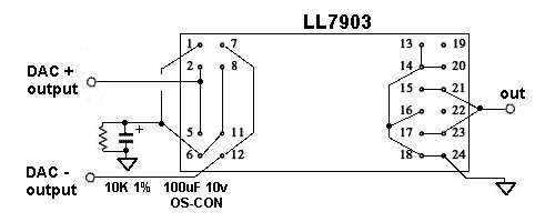
but is is also double the cost of a 1544AS!
So, can I just put a pot or attenuator on the output and I'll be fine?
KR
Teo
thanks again for your help. I don't intend to use long cables.
I've been reading some more about the DAC chip CS4397 and found the following project with a solution similar to yours:
DAC Final
Here the Lundahl LL7903 is chosen because it apparently has less distortion:
but is is also double the cost of a 1544AS!
So, can I just put a pot or attenuator on the output and I'll be fine?
KR
Teo
Hello
Could you please help me with adding stepped attenuator to my circuit ? What is the best place to add it ? What resistance ? I need to change sth in tube circuit ?
I want to drive directly my power amp with this.
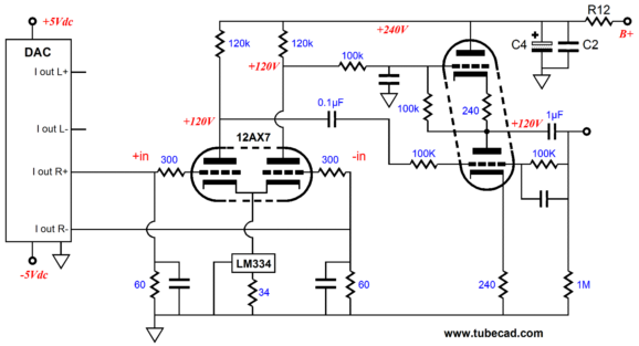
This is 2x PCM1794 in mono mode + tube unbalancer, one channel topology below:
Could you please help me with adding stepped attenuator to my circuit ? What is the best place to add it ? What resistance ? I need to change sth in tube circuit ?
I want to drive directly my power amp with this.
This is 2x PCM1794 in mono mode + tube unbalancer, one channel topology below:
Those resistors to grid i guess are low enough not to produce some grid current distortion, but i'm not sure what's them purpose. I always think about a tranformer at output to isolate and attenuate... mayber a resistive divider after that. If in input try not to put a parallel resistor to RG, as you would be changing Zin.
- Home
- Source & Line
- Digital Line Level
- DAC with tube preamp?