I designed this to provide a USB input for the ezdac (see thread http://www.diyaudio.com/forums/digital-line-level/140383-ezdac-v-1-5-builders-thread.html ). It's based pretty closely to the datasheet app circuit.
I wanted selection of USB or S/PDIF input via a DIP relay, which is controlled from another board that does analog input selection.
Because the PCM2704 provides both S/PDIF and analog outputs, I decided to make the board more versatile (and easier to test) by bringing out the analog outputs. I have 300-ohm headphones which require some gain from the DAC output, so I added opamps at the output. I wanted a bit more headroom than the 5V USB supply provides, so there is a -5V supply generated by a switched-capacitor voltage converter.
I spotted a couple of needed changes already. The two opamps should be in the same package (my last re-annotate broke them up); and I'll reduce the values of the resistors at the output of the opamps to maybe 33 ohms or so.
Comments are welcome.
Attachments
Simpler
Thanks for all your comments and suggestions. I've decided to get rid of the opamps. My thinking is that I'll move them onto a separate companion board that will include a Li-ion battery charger and boost converter, and allow for an MP3 player input or the USB audio.
So, the new schematic is closer to the datasheet's Figure 33. I've beefed up the filtering a bit, and kept the relay to select USB or S/PDIF input. The connector JP2 is for the aforementioned companion board.
I've also added a an output transformer to allow isolation, if needed. For driving the ezdac board, I'll just bypass the transformer because the ezdac has its own input transformer.
I'll be working on the PCB layout for this over the next week or so.
Attachments
Last edited:
I tried a similar USB/SPDIF circuit when i first built the EzDac and didn't enjoy the sound much. For the last couple of years EzDac has been getting I2S from a 2707 and sounds much better.
Is it galvanically connected to the PC?
If so, have you considered a USB isolator?
USB Isolator. « Circuits@Home
The only difference is the S/PDIF output, and I seriously doubt I'd be able to tell the difference. The HagUSB uses the same part:I tried a similar USB/SPDIF circuit when i first built the EzDac and didn't enjoy the sound much. For the last couple of years EzDac has been getting I2S from a 2707 and sounds much better.
Hagerman Technology LLC: HagUsb USB to SPDIF Audiophile Converter
and seems to be popular.
For those that are interested in an an I2S input DAC, there are other (probably more suitable) choices. Here's one:
The γ1 Modular Miniature DAC
USB input is available with this kit.
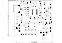
Here's an initial placement for this PCB. USB and S/PDIF inputs on the left (which will be mounted on the rear panel) along with their LEDs; S/PDIF output at the bottom right, headphone output on the right. The schematic has changed slightly, I now have two connectors JP2 and JP3 that will connect to the companion board I referred to. JP1 is 24VDC relay control input.
Attachments
I did consider it, but my current USB DAC uses the standard connector and I didn't see the point in designing something that requires me to buy a new cable.Why not use mini-USB? Does save much on the footprint, but the cables seem to be more readily available.
Paul,
Just curious at this point... are you definitely set on routing the USB into a S-P/DIF conversion?
I am back and forth between several projects, but still planning for USB input to the DAC.
I am also introducing need for a "transparent" HP Amp., so reviewing DAC's output interface with a good OPAmp/volume control scheme driving a discrete transistor amp.
Any suggestions/ guidance re. output amps would be well taken.
Thanks,
Louis
Hi Louis,
I'm still working on this. I'm now planning it for a dual purpose: besides just USB to S/PDIF, it will also have a battery-powered headphone output amp, which could be used as a USB DAC headphone amp, or the headphone amp could be used by itself for an MP3 player. I had planned this as a second board but it ended up being much cheaper to put it all on one board. I'll go with more surface mount parts to fit it all onto a 75 x 120 mm board.
Are you asking about ideas for a power amplifier ( I like the P3A at Elliott Sound Products - The Audio Pages (Main Index)), or about a buffer stage after the ezDAC (I don't think it is required)?
Paul,
I understand you are going for versatility, probably because you are into all the music storage devices out there. So far, I am staying with plans for USB & S/P-dif both to a common I2S interface.
The HP Amp i am currently planning is seen at this site (RED Free designs):
Headphone Amplifier - RED - Page30
I am stuck with the manner of interfacing the DAC's differential output, and may go for a 1:1 transformer coupling to interface an OPAmp buffer w/volume and cross feed components. Cross feed circuit (active) will likely be the Shuffler as described in Richard Kaufman's book Enhanced Sound.
Plan is to PCB all this on one board.
Louis
Forgot to include the information page at which I am reviewing the various Differential to Single ended circuit schemes:
Using Op Amps with Data Converters - Part 5 | Audio DesignLine
Some of those support/explain the "raison d'etre for the EZDac termination components. Quite useful.
Louis
Using Op Amps with Data Converters - Part 5 | Audio DesignLine
Some of those support/explain the "raison d'etre for the EZDac termination components. Quite useful.
Louis
Some of those support/explain the "raison d'etre for the EZDac termination components. Quite useful.
Louis
Yep, you got it. Those circuits are all described in the "Data Conversion Handbook" put out by Analog Devices (available at Amazon.com). I read it extensively when I designed the ezDAC, and it seemed like basically the simplest thing I could do to get sound out the other end, which was my goal.
Data Conversion Handbook
This is also available as PDFs from
ADI - Analog Dialogue | Data Conversion Handbook
This is also available as PDFs from
ADI - Analog Dialogue | Data Conversion Handbook
Actually, I'm going for what will solve my particular requirements. I need a USB-S/PDIF converter board for the ezdac and I would also like a portable DAC / headphone amp. I decided to do both with the same board.Paul,
I understand you are going for versatility, probably because you are into all the music storage devices out there. So far, I am staying with plans for USB & S/P-dif both to a common I2S interface.
Louis
Yes, I know that I can buy other boards for this (e.g. the Gamma-1 DAC), but I already have the ezdac and (for the portable application) would like to customize the PCB for a particular enclosure:
Hammond Mfg. - Extruded Aluminum (Metal End Panels) - 1455 Series Enclosures
I'll build two PCBs, populated differently, for the two applications.
Nothing too special about that circuit, and it would drive 32-ohm headphones nicely with its high output current capability. I'm planning to just use two paralleled opamps per channel to drive my 300-ohm headphones, similar to this:The HP Amp i am currently planning is seen at this site (RED Free designs):
Headphone Amplifier - RED - Page30
Louis
HeadWize - Project: Apheared's Project Scrapbook by Michael Shelton
While I was at that site, I noticed this, kind of similar to your Red Circuits design:
HeadWize: DIY Workshop > Headphones amp based on the ne5534
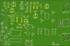
I've made some major changes to the circuit. In addition to its primary function as a USB to S/PDIF converter, it can be built up to create a battery-powered headphone amp. The amp input can be switched between USB or analog (e.g. an MP3 player). The Li-ion battery is switched up to +/- 5V to run the parallelled opamps that drive the headphones, and is charged from the USB power.
The PCB was laid out to fit directly into a Hammond 1457K1201 enclosure.
The PCB was laid out to fit directly into a Hammond 1457K1201 enclosure.
Attachments
Recently I am interested in this little box: Audiophilleo2 - low jitter USB to SPDIF transport,converter
It is a USB-SPDIF converter via asynchronous transfer. With such a transfer mode, its jitter is theoretically lower than the usual PCM27xx-based converters.
It is a USB-SPDIF converter via asynchronous transfer. With such a transfer mode, its jitter is theoretically lower than the usual PCM27xx-based converters.
Price: $495Recently I am interested in this little box: Audiophilleo2 - low jitter USB to SPDIF transport,converter
It is a USB-SPDIF converter via asynchronous transfer. With such a transfer mode, its jitter is theoretically lower than the usual PCM27xx-based converters.
Little ways out of my range.
Last edited:
- Status
- This old topic is closed. If you want to reopen this topic, contact a moderator using the "Report Post" button.
- Home
- Source & Line
- Digital Line Level
- USB-S/PDIF converter and DAC