hello
indeed this appears to me as a very nice and professional work made by Bill Dipoala.
nevertheless i would like to stick with the original behringer I/O boards.
in chosing a tradeoff between minimizing opamps/ stage count versus the approach of symmetrical signal transfer between boards i prefer the last one.
as the opamps used by behringer seem to be pretty sensitive to power supply imperfections i am heading to further improvements concerning the decoupling of the power supply there.
has anyone yet tried to split PS for the different stages on the I/O board ?
greetings
michael
out configuration
the PS layout on the I/O board is organised in a way that the opamps for the outputs 1,2 and 3,4 and 5,6 share the same bypassing condensators.
it really is worth to try different "out configuratios".
for 2 way speakers the "LH LH LH" configuration worked best for me. it excels over the "LL MM HH" in detail and over the "LMH LMT" in soudstage
all in all its one more indicator for the pretty insufficient pcb layout of the PS on the I/O board
greetings
michael
I/O PS decoupling
hello
who is willing to invest some hours of patient work on smd soldering, try to 'individualize" the decoupling of all the out-opamps.
i lifted pin 4 and 8 of the opamps's and connected 10uf to each (24 condensators all in all, placed on a speerate cnstruction board). the other side connect to ground via the corresponding pin1 of the xlr out. the positive and negative rail take from the x14 connector.
as result i gained improved localisation in the stereo image, als well as easier tracking of bass lines and vocals becoming more precise and pesent.
greetings
michael
sorry ric
no photo at the time.
it looks more like some scrapyard (quite contrary to sound) right now as i started with some different values of resistors (though non has proven to be best, which means: lowest limitation in space especially for the low frequency end) to form a true r-c filter from the rails and furthermore this place currently appears to me to be a highly sensitive enviroment, just right to make some tries with differnt types of caps to get even closer to the kind of sound i love.
but even without a picture it is really easy to do.
1. first take a board of about 25 x 160 mm - this will fit nice in between of the I/O and digital behringer boards.
2. keep it in place by soldering some solid 0,8mm wires to one of the xlr pins on the upper side.
3. put your 24 caps of coice onto it and connnect them as i described above.
4. a microminimal improvment can be done by connecting the rails only from one of the pins 5/6, 7/8 of connector x14 (you will have to cut a small trace to the neighbour pin) this will leave two a little bit more "isolated" rail pins for a further mod of the input opamps bypassing
greetings
michael
output using transformer
to petervv
"Just finished major surgery to my DCX, I removed the I/O pcb and
mounted input and out transformers."
Can you explain more about the output using transformers? Witch impedance ?Is there a lundalhl sample good for coupling? Can you make a schematics please?Many thanks...
to petervv
"Just finished major surgery to my DCX, I removed the I/O pcb and
mounted input and out transformers."
Can you explain more about the output using transformers? Witch impedance ?Is there a lundalhl sample good for coupling? Can you make a schematics please?Many thanks...
re: output using transformers
hi balthazard ,
>Can you explain more about the output using transformers? >Witch impedance ?Is there a lundalhl sample good for coupling? >Can you make a schematics please?Many thanks...
I don't think impedance is too important in this application where the transformer is driven from a low impedance opamp output, Thorsten has written several posts on this subject. Check this thread and the DEQ2496 thread in the 'digital' group.
Lundahl has several types of suitable transfomers, look in the DAC/line output section. Transformer ratio depends on how much voltage you need in your chain. I get about 0.5VRMS from my 3:1 transformers and this is enough to drive my poweramps.
regards, Peter
Volume control by voltage control?
What did you think about a volume control for the DCX2496 with only a single one-gang pot for all six channels?
I studied the datasheet of the AK4396 D/A converters. For sure you know a D/A converter is a multiplying device. It multiplies the digital input with the reference voltage. The result of this multiplication is the output signal. This means decreasing the reference voltage also scales down the output signal.
In the data sheet of the AK4396 I found the following text:
Analog output voltage scales with the voltage of (VREFH-VREFL).
AOUT (typ.@0db) = (AOUT+-) - (AOUT-) = +-2,4Vpp*(VREFH-VREFL)/5
At the DCX2496 VREFL is 0V and VREFH 5V. This means the output is +-2.4V. Decreasing VREFH down to 0V also will decrease the output signal swing down to 0V!
So my idea is inserting a pot in the supply for VREFH for all three D/A converters. That’s all. It’s so simple!
But there is another value in the datasheet. It says that VREFH shold not be lass than 0.5V below AVDD which means minimum 4.5V. The question is what will happen below 4.5V? Will the chip die with a cloud of smoke or will it work despite of the limitation in the datasheet? So maybee increasing of VREFL is the better way. There is no maximum voltage for VREFL in the datasheet so it may be inceased up to 5V which also gives an output signal of 0V!
I have not tested this yet and it is not without risk. So think about it carefully before you try. But if it will work it really would be a very cool patch!
Hi petervv,
Some time ago I made a simulation using Microcap of the input stage of the DCX, and found that there was a build-in treble preemphasis.
It is true that this was my first Pspice simulation, so I may be wrong.
Have you made a frequency measurement after the mod?.
Regards
Miguel mentero
Some time ago I made a simulation using Microcap of the input stage of the DCX, and found that there was a build-in treble preemphasis.
It is true that this was my first Pspice simulation, so I may be wrong.
Have you made a frequency measurement after the mod?.
Regards
Miguel mentero
A lack of time has again kept me from posting my results, but I have been messing with a "clever" volume for DCX also.
I have at the moment 2 channels of DCX running so that I take a signal out right after DAC. Then I have a series resistor in both + and - output pins. Between the other ends of resistors is a 10k pot wired as an "adjustable resistor" from about 60ohm to 10kohm.
Check figure 2 on
http://borbelyaudio.com/upgrades.asp
This means that I'm running a balanced shunt regulator right after the DAC. From + terminal after the series resistor I have a 10u cap and then the RCA socket. Additonally I have only a 1000p cap in parallel with pot contacts to form a low pass filter.
That is it - this signal then goes to amp and speakers - and there seems to be no ill effects with more HF crap etc. And the sound is very good. I dragged the unit yesterday to local HiFi shop to get a second opinion and it seems I'm not alone appreciating the sound")
I will post details during next week I hope (and also connect the last 4 channels to my 6ch pot )
Regards,
Ergo
I have at the moment 2 channels of DCX running so that I take a signal out right after DAC. Then I have a series resistor in both + and - output pins. Between the other ends of resistors is a 10k pot wired as an "adjustable resistor" from about 60ohm to 10kohm.
Check figure 2 on
http://borbelyaudio.com/upgrades.asp
This means that I'm running a balanced shunt regulator right after the DAC. From + terminal after the series resistor I have a 10u cap and then the RCA socket. Additonally I have only a 1000p cap in parallel with pot contacts to form a low pass filter.
That is it - this signal then goes to amp and speakers - and there seems to be no ill effects with more HF crap etc. And the sound is very good. I dragged the unit yesterday to local HiFi shop to get a second opinion and it seems I'm not alone appreciating the sound
I will post details during next week I hope (and also connect the last 4 channels to my 6ch pot
)Regards,
Ergo
ergo said:That is it - this signal then goes to amp and speakers - and there seems to be no ill effects with more HF crap etc. And the sound is very good. I dragged the unit yesterday to local HiFi shop to get a second opinion and it seems I'm not alone appreciating the sound
Regards,
Ergo
That certainly is it. I did the similar thing - ran the signal straight from DAC to my passive preamp and than to amp. What a difference comparing to existing opamps. This certainly is the best mod that could be done. I am sure your simple filter does all it is needed to filter out HF.
Enjoy
AR2
re: Pspice simulation
hi Miguel,
Some time ago I made a simulation using Microcap of the input stage of the DCX, and found that there was a build-in treble preemphasis.
I haven't checked the schematic for this, but it would surprise me if there was a treble preemphasis buildt in, I can't think of any reason doing so.
Have you made a frequency measurement after the mod?.
No I haven't, I only use the analog input for tuner en turntable, the tuner (Pioneer 8500II) sounds better than ever, most of my 45's will never sound good
regards, Peter
Hi Peter,
Don't ask me. In any case, good to know it´s working for you.
All the best
Miguel mentero
I haven't checked the schematic for this, but it would surprise me if there was a treble preemphasis buildt in, I can't think of any reason doing so.
Don't ask me. In any case, good to know it´s working for you.
All the best
Miguel mentero
Regarding a treble pre-emphasis: I think you fellas need to recheck your simulations.
I did a simulation a long time ago when the schematics first became available and I see no pre-emphasis....only filtering above and below the audio band and DC blocking. I later confirmed this with actual measurements and everything looked as expected.
Cheers,
Davey.
I did a simulation a long time ago when the schematics first became available and I see no pre-emphasis....only filtering above and below the audio band and DC blocking. I later confirmed this with actual measurements and everything looked as expected.
Cheers,
Davey.
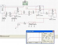
Well.. Maybe I got something wrong. I double checked the circuit and could not find any errors. The frequency of the emphasis changes when changing the values of the components in the bias section. Trying to attach a screenshot.
// Lyckman
// Lyckman
Attachments

Fredrik,
Yes, I stand corrected. My simulation also shows this...(I had the wrong component value entered for C4.)
However, an actual in/out transfer function measurement (DCX programmed flat) doesn't show this shelved response. There must be an equivalent "de-emphasis" somewhere along the way that counters it. I took a quick look at the remaining analog circuitry and I don't see it. Maybe something in the DSP?
Cheers,
Davey.
Filter caps removed and as suspected, the response is now flat in the sim.
This is wierd. Why would one do an analog preemphasis and then (probably) a digital de-emphasis in the DSP? And further, you'll need a different "program" in the DSP when using the digital input instead (eg no filter).
I've done some measurements some time ago, bypassing the input stage with analog signal straight to the ADC's, but I can't remember that I noticed anything similar to what the schematics is applying. (one should notice a 5dB loss of the signal above 5khz, right )
Could the schematics be wrong? Can anyone confirm the values on the components? Maybe you accidently inserted the correct values for the cap(s) in your sim, davey?
// Lyckman
This is wierd. Why would one do an analog preemphasis and then (probably) a digital de-emphasis in the DSP? And further, you'll need a different "program" in the DSP when using the digital input instead (eg no filter).
I've done some measurements some time ago, bypassing the input stage with analog signal straight to the ADC's, but I can't remember that I noticed anything similar to what the schematics is applying. (one should notice a 5dB loss of the signal above 5khz, right
)Could the schematics be wrong? Can anyone confirm the values on the components? Maybe you accidently inserted the correct values for the cap(s) in your sim, davey?
// Lyckman
Attachments
- Home
- Source & Line
- Digital Line Level
- Behringer DCX2496 digital X-over