AR2.
Thank you, that was just what I was looking for.
I'll study your drawing and look up your transformers on the K&K site. I have dealt with Kevin in the past. You are correct, very helpful.
The one thing I haven't figured out is the analog pin out.
By the way, did you modify the inputs as well?
And if you removed the Audio board, did you do something for the RS232 Circuitry?
Doug
Doug,
Go few pages back, you will see my latest mods explained with pictures. As you will learn I have eliminated analog inputs as I am not using them. I have Jan Diden's passive board that I am using just to rout signal to XLRs. What I did before was something that you could do as well - cut XLR connectors to the board and wire them to underside of X13 26 pin connector. It is not pretty but it works. It did for me last few years, before Jan's board. That way you will preserve inputs and RS232. Jan's board is really sweet and you might want to look into it if you could live without analog inputs. If not - be creative.
Problem is that with all that you cannot place transformers inside the case.
That is why I decided to place Lundahs in the separate case which holds: Lundahls, digitaly controled passive volume control and 4 XBOSOZ boards. I have it all balanced so I use XLR cables to connect it all. Check it out here:
http://www.diyaudio.com/forums/showthread.php?postid=872582#post872582
You will see there all that I was talking. Regarding pin out question, do you have Behringer schematic? If not I will email you. Let me know. I am thinking down the line to make a board that will house Lundahls inside the DCX (with the little help of my friend Choky), but that will take some time until I put it all together.
AR2
AR2,
Thank you. I have been reading the thread from the beginning.
I would love a Schematic. Dougl at Speakeasy dot net.
I have had the DCX for a couple of years now, and have been using the analog inputs to date.
What you are doing looks wonderful.
Thanks again for the help.
Doug
Thank you. I have been reading the thread from the beginning.
I would love a Schematic. Dougl at Speakeasy dot net.
I have had the DCX for a couple of years now, and have been using the analog inputs to date.
What you are doing looks wonderful.
Thanks again for the help.
Doug
To celebrate the last days of the year a few more interesting results posted about the modifications to DCX2496
Installing Frank's regulator mod
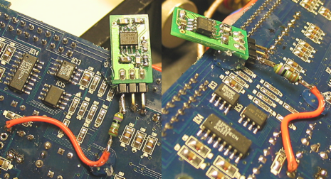
Ergo
Installing Frank's regulator mod
Ergo
Ergo,
Thanks, quite interesting! I will also try out the foil thing.
One comment of you struck me: that the sound seemed to become 'loose' from the speakers, because I had exactly the same impression after the installation of Franks' mods (digital input & low noise reg).
Next attack: the power supply!
Jan Didden

Well I finally ordered myself a DCX2496. This will be replacing my Rane AC22B and probably my DEQ1024 as well, but not 100% sure on that one yet. I'll be using it to do xover, delay, EQ, etc, etc duty across the front three channels (L/C/R) of my home theater/2-channel system. I also ordered an AudioSource AMP100 so I can bi-amp the center channel. 
Hi AR2,
I’ve reproduced the following of your mods:
1. Replace DACs AK4393 with AK4396
My expectations have been rather low because the AKM data sheets only show two relevant differences. Power consumption is reduced from 310mW to 200mW http://www.asahi-kasei.co.jp/akm/en/product/ak4396/ak4396_f00e.pdf (page 4) and out of band noise is somehow reduced http://www.akm.com/images/ak4396 graphic.htm . Measurement diagrams don’t show substantial differences http://www.asahi-kasei.co.jp/akm/en/product/ak4393/akd4393e.pdf and
http://www.asahi-kasei.co.jp/akm/en/product/ak4396/akd4396-sbw2-02e.pdf .
The mod is pretty easy. You just have to disassemble the three AK4393s and to assemble the AK4396s.
Although not expected I would say there is a small improvement. To my opinion sound became more accurate and realistic. So I would say it’s worth doing this mod.
2. Replace digital input transformer
I replaced the original DCX transformer by a low jitter SC947 transformer http://www.scientificonversion.com/catalog.html . I compared the different transformers to my second optical digital input. I haven’t been able to hear any difference before and after the mod. That might be different with higher sample rates e.g. 96 kHz and other input sources.
Hi Ergo,
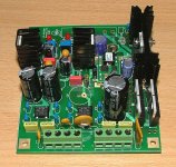
I made some measurements with a scope at the original DCX supply http://www.awdiy.com/uploads/pdf/DEQ2496-PSU-1.5.pdf . There is an about 400 mVpp noise on each of the three analog +/-15V and +9V rails but not on the two digital +3.3V and +5V rails. Looking at the schematic reason is that the two digital rails have a pi-filter (CLC) at their output and the analog rails not. The used regulators 7815/7915 and 7805 can’t reject this HF noise and transmit it to the ADCs, DACs and opamps. This noise is an out of band noise (>20 kHz). I can’t say whether this HF noise is sonical relevant.
Regarding your RF shielding I’m still wondering which components could be transmitter and which receiver of this RF noise. Sampling frequency of the front panel is about 150 Hz. So it would be interesting whether RF noise can be reduced by simply disconnecting front panel (flat cable).
Regards, Frank
I’ve reproduced the following of your mods:
1. Replace DACs AK4393 with AK4396
My expectations have been rather low because the AKM data sheets only show two relevant differences. Power consumption is reduced from 310mW to 200mW http://www.asahi-kasei.co.jp/akm/en/product/ak4396/ak4396_f00e.pdf (page 4) and out of band noise is somehow reduced http://www.akm.com/images/ak4396 graphic.htm . Measurement diagrams don’t show substantial differences http://www.asahi-kasei.co.jp/akm/en/product/ak4393/akd4393e.pdf and
http://www.asahi-kasei.co.jp/akm/en/product/ak4396/akd4396-sbw2-02e.pdf .
The mod is pretty easy. You just have to disassemble the three AK4393s and to assemble the AK4396s.
Although not expected I would say there is a small improvement. To my opinion sound became more accurate and realistic. So I would say it’s worth doing this mod.
2. Replace digital input transformer
I replaced the original DCX transformer by a low jitter SC947 transformer http://www.scientificonversion.com/catalog.html . I compared the different transformers to my second optical digital input. I haven’t been able to hear any difference before and after the mod. That might be different with higher sample rates e.g. 96 kHz and other input sources.
Hi Ergo,
I made some measurements with a scope at the original DCX supply http://www.awdiy.com/uploads/pdf/DEQ2496-PSU-1.5.pdf . There is an about 400 mVpp noise on each of the three analog +/-15V and +9V rails but not on the two digital +3.3V and +5V rails. Looking at the schematic reason is that the two digital rails have a pi-filter (CLC) at their output and the analog rails not. The used regulators 7815/7915 and 7805 can’t reject this HF noise and transmit it to the ADCs, DACs and opamps. This noise is an out of band noise (>20 kHz). I can’t say whether this HF noise is sonical relevant.
Regarding your RF shielding I’m still wondering which components could be transmitter and which receiver of this RF noise. Sampling frequency of the front panel is about 150 Hz. So it would be interesting whether RF noise can be reduced by simply disconnecting front panel (flat cable).
Regards, Frank
I hope to do the STOCK versus MODIFIED DCX2496 measurements tomorrow - have both units at home and awaiting.
The plan is to do at least following
noisefloor
freq resp
THD
IMD
Dunn Jitter signal
if time allows also 44.1kHz and 48kHz comparison. Due to odd complications I can not create 96kHz SPDIF for DCX with neither soundcard I have
So hopefully I will have these results up tomorrow.
Ergo
The plan is to do at least following
noisefloor
freq resp
THD
IMD
Dunn Jitter signal
if time allows also 44.1kHz and 48kHz comparison. Due to odd complications I can not create 96kHz SPDIF for DCX with neither soundcard I have
So hopefully I will have these results up tomorrow.
Ergo
oettle said:
I made some measurements with a scope at the original DCX supply http://www.awdiy.com/uploads/pdf/DEQ2496-PSU-1.5.pdf . There is an about 400 mVpp noise on each of the three analog +/-15V and +9V rails but not on the two digital +3.3V and +5V rails. Looking at the schematic reason is that the two digital rails have a pi-filter (CLC) at their output and the analog rails not. The used regulators 7815/7915 and 7805 can’t reject this HF noise and transmit it to the ADCs, DACs and opamps. This noise is an out of band noise (>20 kHz). I can’t say whether this HF noise is sonical relevant.
Hi Oettle!
Not sure that the PI filter is solving all noise problem. On my linear PSU, I first included a PI filter on the analog rail and after more testing, the noise floor was lower without the PI filter. 7815/7915 are not the best regulators for noise too.
With the linear PSU, +-15v and 3.3v are around 15mVpp noise, the +5V is below 30mVpp. If you replace the 7805 on the DSP board with a low noise regulator, you go further too.
With the linear psu, the difference is not only lower noise. Dynamic and high frequencies are also better. I received 3 reports from diyers with the same opinion.
For the one who use the DCX in analog way, I would also suggest to change the op-amp before going with the passive solution. It's a pain to do but very very efficient. I suggest LM4562 for input circuits and buffers, and OPA2134 for the DAC output (or better a double OPA827). Passive solution is in theory very fine but is not very dynamic and bandwidth not really flat.
Stephane
Hi Stephane,
You are right you can’t reduce all noise with a pi-filter but you can reduce noise depended on its frequency. With the proposed 100µH coil and a 220µF cap noise reduction @ 100 kHz is about 40-50 dB. So the 400 mVpp noise can be reduced to something about a few mVpp and it’s getting difficult to measure the remaining noise with a scope at all.
PSRR of the AK4393 is 50 dB and that of a standard 7805 is about 50-60 dB within sonically frequency range. That might be the reason why Ergo can’t see any improvements @10Hz-20kHz. Above 20 kHz this should be different because PSRR of the standard 7805 regulators get worse. Remaining question would be whether this out of band noise is sonically relevant at all?
Regarding PSU modding I didn’t understand benefit of improving +3.3V and +5V rails so far. These rails aren’t used by a single analog component. They supply digital components only. I’m using 3 DCX for several years and I’m not aware that DSP failed nor have I heard about such a problem.
But noise is an issue for the +/-15V and +9V supplies which are used mainly by analog components (DACs, ADCs, opamps).
Regards, Frank
oettle said:Hi AR2,
I’ve reproduced the following of your mods:
1. Replace DACs AK4393 with AK4396
My expectations have been rather low because the AKM data sheets only show two relevant differences. Power consumption is reduced from 310mW to 200mW http://www.asahi-kasei.co.jp/akm/en/product/ak4396/ak4396_f00e.pdf (page 4) and out of band noise is somehow reduced http://www.akm.com/images/ak4396 graphic.htm . Measurement diagrams don’t show substantial differences http://www.asahi-kasei.co.jp/akm/en/product/ak4393/akd4393e.pdf and
http://www.asahi-kasei.co.jp/akm/en/product/ak4396/akd4396-sbw2-02e.pdf .
The mod is pretty easy. You just have to disassemble the three AK4393s and to assemble the AK4396s.
Although not expected I would say there is a small improvement. To my opinion sound became more accurate and realistic. So I would say it’s worth doing this mod.
2. Replace digital input transformer
I replaced the original DCX transformer by a low jitter SC947 transformer http://www.scientificonversion.com/catalog.html . I compared the different transformers to my second optical digital input. I haven’t been able to hear any difference before and after the mod. That might be different with higher sample rates e.g. 96 kHz and other input sources.
Regards, Frank
Hello Frank, from stormy Northern California. I just got power after 1 and 1/2 day of outage. Regarding DACs that is exactly how I felt about exchange of DAC chips. There is difference, slight and mostly heard in high frequencys. Not a day or night but worth doing.
Regarding digital transformer, I believe it is not such a mod that could be heard with all other mods installed. Since Jon and Scientific Conversion is literary in my neighboroughood I had a opportunity to visit them and to have a demonstration on very sophisticated HP jitter measurement unit. Jon has big collection of various digital transformers for comparison. It was an eye opener. With simple replacement of various transformers in the same test board, instrument was showing jitter reading. The difference was tenfold.
Just exchanging digital transformer is not going to make a bad design a good one. In the case of Behringer it most likely lowers jitter at one step, and than everything else contribute to the sound.
I am glad that you found improvement with new DACs.
Cheers
AR2
Hi AR2,
You are right my experience with the S/PDIF transformer is based on my own SRC/clock mod. With the original CS8420 it might be different although I think jitter before the SRC isn't such important as long as PLL is able to lock properly because of reclocking.
That seems to be completely different on the secondary side of the SRC. The DACs obviously need to have a low jitter clock.
Frank
AR2 said:
Hello Frank, from stormy Northern California. I just got power after 1 and 1/2 day of outage. Regarding DACs that is exactly how I felt about exchange of DAC chips. There is difference, slight and mostly heard in high frequencys. Not a day or night but worth doing.
Have you tried to play with CKS pins? On the original design, the setting is pins 26, 27 and 28 connected to ground. It can be interesting to try disconnecting pin 28 and 27 from ground with AK4396.
- Home
- Source & Line
- Digital Line Level
- Behringer DCX2496 digital X-over