Behringer say pins 1 and 3 should be shorted for an unbalanced input, however, it has a cross coupled output so presumably cold could be connected to RCA shield on its own?
I think it should. Ideally, the RCA input should be carried all the way to the input board and grounded at the circuit ground, for instance the bottom of a feedback resistors. The unit should already have a connection from circuit ground to chassis and you don't want to mess with that.
But for practical reasons you may have no choice.
DCX2496 active output mod & 6-channel vol control | Linear Audio NL
Jan
Good old 10Base2 days where earthing both ends resulted in probable network failures, a 300$ unit plus a couple extra dollars of modding + fun + learning = diyaudio, but you could just buy a better alternative sit back enjoy your music while flipping pancakes
Yes that will work, perfect. Many people connect the screen to ground at the receiving end also, but that is not recommended. In that case there is still a small chance on hum because the slightly different ground potential * between the two chassis is equalized through the screen and that current can induce hum in the signal lead. But if it works it works.
Also, in the DCX all balanced is pseudo-balanced so it still is referenced to gnd, so 'real' balanced is not available anyway.
Jan
* due to things like different mains leakage due to different mains transformers and ground points.
Last edited:
Good old 10Base2 days where earthing both ends resulted in probable network failures
.... synchronized to the airco cutting in or out

Greetings from the "hot spot" Donetsk (Ukraine).
Integrated into DCX2496 - relay six-channel volume control, as well as 3 additional digital inputs TOSLINK. Removed capacitors C43-48, transistors T1-6. Operational amplifiers IC1B-IC6B are converted to a single gain. On / off control, input selector and volume from the remote control. All power capacitors are replaced by polymer
Video YouTube
An externally hosted image should be here but it was not working when we last tested it.
An externally hosted image should be here but it was not working when we last tested it.
An externally hosted image should be here but it was not working when we last tested it.
Greetings from the "hot spot" Donetsk (Ukraine).
Integrated into DCX2496 - relay six-channel volume control, as well as 3 additional digital inputs TOSLINK. Removed capacitors C43-48, transistors T1-6. Operational amplifiers IC1B-IC6B are converted to a single gain. On / off control, input selector and volume from the remote control. All power capacitors are replaced by polymer
Very impressive! I have a couple of those boards as well. I have several questions about your implementation - how did you integrate the attenuators into the signal path, was it in place of electrolytic decoupling capacitors on the output board?
Second, how in the world did you hijack the main rotary encoder?
Third, how do you control these boards? Last time I checked (which was at least 4 years ago) you needed either an analog voltage or emulate remote IR protocol through digital pin. Did the firmware get upgraded for easier control via microcontroller?
Very impressive! I have a couple of those boards as well. I have several questions about your implementation - how did you integrate the attenuators into the signal path, was it in place of electrolytic decoupling capacitors on the output board?
Yes, just like that (as in the picture). These capacitors are not really needed.
Second, how in the world did you hijack the main rotary encoder?
Everything is very simple. The encoder does not need to be cracked, I added a latching relay, which in the desired mode connects pins A and B of the encoder to the volume control controller. This does not prevent the use of the encoder to control DCX2496
Third, how do you control these boards? Last time I checked (which was at least 4 years ago) you needed either an analog voltage or emulate remote IR protocol through digital pin. Did the firmware get upgraded for easier control via microcontroller?
The volume control is controlled by a separate controller, which allows you to use both the IR receiver and the Enecoder, or the buttons, as you prefer. If you know how to use a translator, more about it here:
????????? ????????? ???????? ? ?? ?? antecom
????? ???????
Perhaps the author has a description in English, you need to clarify. His mail vmaudio@mail.ru
Attachments
Yes, just like that (as in the picture). These capacitors are not really needed.
Everything is very simple. The encoder does not need to be cracked, I added a latching relay, which in the desired mode connects pins A and B of the encoder to the volume control controller. This does not prevent the use of the encoder to control DCX2496
The volume control is controlled by a separate controller, which allows you to use both the IR receiver and the Enecoder, or the buttons, as you prefer. If you know how to use a translator, more about it here:
????????? ????????? ???????? ? ?? ?? antecom
????? ???????
Perhaps the author has a description in English, you need to clarify. His mail vmaudio@mail.ru
If you want to go out unbal/RCA why not use the output of IC3B. Saves a couple ICs in the signal part.
Jan
Thank you, no need for translation, I'm fluent in Russian. Did you write your own firmware or used someone else's code? Also that's a nice display you got there squeezed in memory card's slot!
Do you know if these kits are still for sale?
If you are fluent in Russian, you can read the documentation on the device. The indication and photodetector had to be placed on a separate board, since small window. By the way, you can use any other volume control, for example on a motorized six-channel potentiometer with aliexpress. In this case, the resistors of the second operational amplifier will need to be increased. But in this case the encoder does not apply and there will be problems with the indication. In my set it is possible to quickly adjust the levels of low, medium and high frequencies from the console.
Kits are sold, the seller’s mail was written above, and he is the developer of the code. Documentation for the kit in Russian by reference http://forum.vegalab.ru/attachment.php?attachmentid=226661&d=1420975564
If you want to go out unbal/RCA why not use the output of IC3B. Saves a couple ICs in the signal part.
Jan
I decided to keep the possibility of both a balanced and unbalanced connection, and I didn’t want to redo much. If you install RCA connectors, then it is easier to completely change the board, improving its routing and applying a different adder circuit after the DAC.
OK, sorry not to be clear. I only suggested to connect the wires you put in at another point, thus saving a couple of ICs in the signal path. No other changes than you did.
But if you don't mind the extra ICs, that's fine of course.
When I did my own extensive mod with the remote vol/bal control for the DCX2496, I realized that shortest signal path is important for best results.
Jan
But if you don't mind the extra ICs, that's fine of course.
When I did my own extensive mod with the remote vol/bal control for the DCX2496, I realized that shortest signal path is important for best results.
Jan
Last edited:
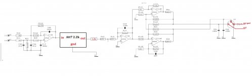
attached is the right way to do balanced inputs. Invert one line and sum it with the other. Try it out, comments welcome
You only need one opamp - opamps have differential inputs.
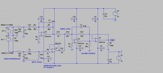
Looks like R1 is actually supposed to be a pot - note how it's labeled VOLUME CONTROL.Same comment as to the previous mod - why the extra opamp at the end? Buffering one opamp with another one
You can get pot models in the LTspice group's files section, at least I think that's where I obtained mine.
attached is the right way to do balanced inputs. Invert one line and sum it with the other. Try it out, comments welcome
if you have one stage doing the inversion that will cause a delay in that line. if the other stage does not go thru an amp stage, it will suffer no delay.
won't that asymmetrical delay pattern cause distortion? ideally, you want both stages to be 'concluded' at the same time, yes?
maybe an allpass to create a similar delay, so that they come together at the same time?
The delay in one opamp stage is practically negligible. But if you look carefully at the posted schematic, you’ll see that there is an opamp in both the hot and cold lines, one inverting and one non-inverting. So if there was a delay in the opamp, it would be consistent on both lines.
Anyway, I agree with jan.didden, there are too many opamps in there.
Anyway, I agree with jan.didden, there are too many opamps in there.
Last edited:
Yes Jan there are two many opamps in there, however you will note that part of the members here cringed on seeing those large input caps so the topology still has some polishing to do by probably adding one or more opamps to tweak the topology to work with 10uf or lower, others may want to completely do away with caps by adding dc servos by this time we have a little more opamps, we can do away with u1 which provides volume control, so this is the balanced input in its simplest form.
Thanks Julf differential inputs of opamps have been misused for a long time as balanced line receivers and mixers. The circuit above is doing it correctly.
Thanks Julf differential inputs of opamps have been misused for a long time as balanced line receivers and mixers. The circuit above is doing it correctly.
Same comment as to the previous mod - why the extra opamp at the end? Buffering one opamp with another one
Jan
- Home
- Source & Line
- Digital Line Level
- Behringer DCX2496 digital X-over