A new run of these boards is now available! Please see the following thread for details:
http://www.diyaudio.com/forums/soli...ble-here-bal-bal-se-se-lpuhp.html#post3516741
Hi Guys,
After having messed around for quite a while with several variations of Nelson's D1 with various modern DACs, I've finally come up with one that I think is worthy of being posted for everyone to use.
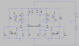
I've combined the excellent transconductance of a power mosfet, with the low distortion of a JFET buffer to get to the circuit below. It's basically a low impedance D1, with a different mosfet, and a B1 buffer in place of the old mosfet based buffer. You could probably call it a D1B1.
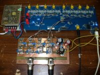
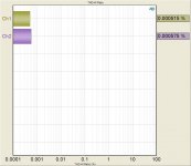
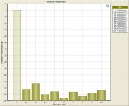
The circuit below provides about 2 VRMS at 0dBFS output when used with a ES9006 run in stereo mode. Performance is superb, and all the measurements are attached. THD+N is 0.000515% (-105.5dB) at 1kHz -8dBFS. This is without matched fets, and a seriously kludged home-made PCB, which means it can be made better with a decent implementation. Even the way it is, I think it sounds excellent.
This circuit could easily be adapted to work with any DAC, and provide almost any gain needed. The gain was set so low to minimize voltage swing at the DAC output.
The source of the mosfet sits at 1.65V which is what the DAC wants to see, and the drain sits at a little over 9 volts which allows direct coupling of the B1 input to the drain. Gain can easily be increased by increasing the value of R1, R2, R3, and R4 while maintaining the same ratio.
I'll be starting a PCB layout with this circuit and the ES9018 DAC which should provide some pretty incredible performance.
Anyone feel like helping with the digital side of the DAC?
Cheers,
Owen
http://www.diyaudio.com/forums/soli...ble-here-bal-bal-se-se-lpuhp.html#post3516741
Hi Guys,
After having messed around for quite a while with several variations of Nelson's D1 with various modern DACs, I've finally come up with one that I think is worthy of being posted for everyone to use.
I've combined the excellent transconductance of a power mosfet, with the low distortion of a JFET buffer to get to the circuit below. It's basically a low impedance D1, with a different mosfet, and a B1 buffer in place of the old mosfet based buffer. You could probably call it a D1B1.
The circuit below provides about 2 VRMS at 0dBFS output when used with a ES9006 run in stereo mode. Performance is superb, and all the measurements are attached. THD+N is 0.000515% (-105.5dB) at 1kHz -8dBFS. This is without matched fets, and a seriously kludged home-made PCB, which means it can be made better with a decent implementation. Even the way it is, I think it sounds excellent.
This circuit could easily be adapted to work with any DAC, and provide almost any gain needed. The gain was set so low to minimize voltage swing at the DAC output.
The source of the mosfet sits at 1.65V which is what the DAC wants to see, and the drain sits at a little over 9 volts which allows direct coupling of the B1 input to the drain. Gain can easily be increased by increasing the value of R1, R2, R3, and R4 while maintaining the same ratio.
I'll be starting a PCB layout with this circuit and the ES9018 DAC which should provide some pretty incredible performance.
Anyone feel like helping with the digital side of the DAC?
Cheers,
Owen
Attachments

Last edited:
Hi Owen
Now that hits the spot- many thanks indeed! Now all we need is for someone to produce a pcb. Though it looks so promising, I may try lashing it up on stripboard
Have you listened to it in comparison to Twisted Pear's IVY implementation on their Buffalo 32S?
Paul
Paul
Now that hits the spot- many thanks indeed! Now all we need is for someone to produce a pcb. Though it looks so promising, I may try lashing it up on stripboard
Have you listened to it in comparison to Twisted Pear's IVY implementation on their Buffalo 32S?
Paul
Paul
Hi Paul,
I've compared it to my Resolution Audio CD50, to the stock ESS reference board for the ES9006, as well as a reference AK4399 and a reference CS4398. I find it sounds better than all of them, and I also find the ESS DAC to be better than the AK or the CS parts. I don't have any of the Twisted Pear stuff here, so I can't compare it to that. Personally though, I don't like the use of op-amps where simple discrete circuitry can provide the same functionality with better performance. Just my opinion though.
I'm already halfway through a PCB layout, but I'm not sure how to handle the PSU options. Discrete PSU's for each channel will be used, but people seem fussy about what regulators they like. I personally would only insist that they be on the PCB itself, and not wired from separate boards. The circuit shown uses simple adjustable linear regs (LM337/317) to get the +/-18V, which if implemented correctly, work quite well. Any suggestions on a favorite regulator would be appreciated.
My PCB will also have the DAC and all PSU's onboard, but I can always spin a separate board with just the output stage if there's interest.
To answer your question from the other thread:
For SE DAC output applications, just half the circuit should work perfectly. You'll end up with a phase inversion, and higher 2nd order distortion, but the former is easy to deal with on the DAC, and the latter is par for the course with SE.
If you mean SE output from a balanced DAC, then you might need to try a few different things. You could send the balanced output to an op-amp/filter and get SE that way, or you could drive a transformer directly. The low impedance voltage output of this IV stage would be much more suitable for driving a 1:1 transformer (compared to directly off the DAC). If you had a 1:1:1:1 transformer you could get away with only one cap between the two series primary windings, and eliminate the two coupling caps at the outputs of the buffers.
There's also the possibility of just taking one of the two outputs of the balanced connection to ground, but I haven't tried it yet, and distortion might be high. I'll give it a shot and I'll let you know.
There are several other discrete options, and I'll take a look into it since it seems to be a popular request with other DACs.
Cheers,
Owen
I've compared it to my Resolution Audio CD50, to the stock ESS reference board for the ES9006, as well as a reference AK4399 and a reference CS4398. I find it sounds better than all of them, and I also find the ESS DAC to be better than the AK or the CS parts. I don't have any of the Twisted Pear stuff here, so I can't compare it to that. Personally though, I don't like the use of op-amps where simple discrete circuitry can provide the same functionality with better performance. Just my opinion though.
I'm already halfway through a PCB layout, but I'm not sure how to handle the PSU options. Discrete PSU's for each channel will be used, but people seem fussy about what regulators they like. I personally would only insist that they be on the PCB itself, and not wired from separate boards. The circuit shown uses simple adjustable linear regs (LM337/317) to get the +/-18V, which if implemented correctly, work quite well. Any suggestions on a favorite regulator would be appreciated.
My PCB will also have the DAC and all PSU's onboard, but I can always spin a separate board with just the output stage if there's interest.
To answer your question from the other thread:
What's the best way in your opinion to use the circuit with single ended-input amps?
For SE DAC output applications, just half the circuit should work perfectly. You'll end up with a phase inversion, and higher 2nd order distortion, but the former is easy to deal with on the DAC, and the latter is par for the course with SE.
If you mean SE output from a balanced DAC, then you might need to try a few different things. You could send the balanced output to an op-amp/filter and get SE that way, or you could drive a transformer directly. The low impedance voltage output of this IV stage would be much more suitable for driving a 1:1 transformer (compared to directly off the DAC). If you had a 1:1:1:1 transformer you could get away with only one cap between the two series primary windings, and eliminate the two coupling caps at the outputs of the buffers.
There's also the possibility of just taking one of the two outputs of the balanced connection to ground, but I haven't tried it yet, and distortion might be high. I'll give it a shot and I'll let you know.
There are several other discrete options, and I'll take a look into it since it seems to be a popular request with other DACs.
Cheers,
Owen
You certainly have my interest for a separate board with the output stage!My PCB will also have the DAC and all PSU's onboard, but I can always spin a separate board with just the output stage if there's interest.
Nic
Hi Owen
All good stuff. I certainly wouldn't normally use op amps in my system- it's only just recently I accepted FETS as useful assistants to triodes! But I wanted to try the Sabre chip, and the Twisted Pear Buffalo 32S is how I "chose" to do it (actually Nic forced me into a corner with the logic of his argument.... 🙂 )
I may try the circuit with DIYParadises' Monica NOS DAC (which aleady uses a discrete I/V design). But, yes, I was mainly asking about getting a SE output from the circuit used wit he the Sabre 9018, and so will be very interested in your findings when you try taking one balanced output to ground (I had hoped that the way you'd drawn your circuit, with each current output half referenced to ground, meant you were confident of this approach working!)
I'm a great fan of Paul Hynes' regs BTW
Keep up the good work, and put me down for any pcb too
THanks
Paul
Last edited:
Owen, I have an idea to make a modular design between your pcb & ACKO's Sabre DAC board - here's my post from the Buffalo tweakers thread in response to qusp wishing that the tweakers board had something to plug into it by which I assumed he meant an output stage:
I have an idea about that - basically to allow output boards to be plugged in from the top into the tweakers board using standard (low impedance) pin connectors i.e a 3D design. I reckon this would give the shortest path to the output stage (probably shorter than the Buff with on-board o/p stage?) & would be stable with 8-10 pins on each side PLUS would make it modular - just plug in another IV stage or whatever as long as it has the correct standard socket I'll be floating this one with Acko & Owen
What do you think?
Hi jkeny,
That would probably be the best way to go if people want to be able to swap various stages. We would just need to come up with a standard pinout for the connector, and I think that should be optimized based on the DAC outputs. With good layout, you could probably keep those connections to less than half an inch which would be about as good as having it on the same board.
I'm guessing the standard 0.1" pitch inline connectors would be the best bet, but I'm open to suggestions. I have seem much more expensive and finer pitch connectors for video applications, but that might just complicate things for people.
Maybe another two connectors one either side of the IV stage could be used for swapping regs for the +/- 18V. I'll look into it.
I should have the layout mostly finished by the end of this weekend so I'll post a preliminary version for comments.
Cheers,
Owen
Building a symmetrical psu B1 buffer
If I may throw my 2 cents into this. I'm no EE
so maybe this isn't possible with the D1 half of
your design. 🙄 However, would it be possible to
cobble the D1 with the "symmetric psu B1"
thus eliminating coupling caps? Also, builders
of this shunt regulated B1 seem to be unanimous
in their praise of it! 🙂
http://www.diyaudio.com/forums/pass-labs/145201-building-symmetrical-psu-b1-buffer.html
If I may throw my 2 cents into this. I'm no EE
so maybe this isn't possible with the D1 half of
your design. 🙄 However, would it be possible to
cobble the D1 with the "symmetric psu B1"
thus eliminating coupling caps?
Given the DAC output is around ground potential you'll have DC above the MOSFET, you have to get rid of it, which is most easily done with a cap, sorry.
One of these days I plan on doing something similar (B1 output), but I'll likely attempt a lovoltech/qspeed JFET instead of a MOSFET - but need to finish other projects 1st. Nice work BTW

Looking at this circuit again has me wondering: why are the filter caps, C7/C8 here, tied to the positive rail instead of ground? Seems like an opportunity for PS noise to creep in. I suppose something to do with the fact that the output signal is created across the resistor and therefore the filter cap should therefore be across the same nodes?
Any particular reason you loaded the output so much with 1K output resistors?
Any particular reason you loaded the output so much with 1K output resistors?
Given the DAC output is around ground potential you'll have DC above the MOSFET, you have to get rid of it, which is most easily done with a cap, sorry.
How about if the dc blocking cap were moved to the input of the B1 circuit and using Salas's symetric B1. Then a smaller(affordable) high quality cap could be used instead. I don't know if the input cap at that circuit point loads it too much?
......Anyone feel like helping with the digital side of the DAC?
Cheers,
Owen
awesome!!!! this is exactly the sort of thing I had in mind as one of the options. I had transformer coupling in mind too as another 'module' but I have been eyeing off the B1 buffer (what can I say; I like nice caps 😉 niot always, but I have a weakness) sio yes I think this and the acko dac would make great partners and I would be interested for sure; I think it easier to keep a wider pitch on the pin headers though, to keep it more flexible.
Owen, I have an idea to make a modular design between your pcb & ACKO's Sabre DAC board - here's my post from the Buffalo tweakers thread in response to qusp wishing that the tweakers board had something to plug into it by which I assumed he meant an output stage:
I have an idea about that - basically to allow output boards to be plugged in from the top into the tweakers board using standard (low impedance) pin connectors i.e a 3D design. I reckon this would give the shortest path to the output stage (probably shorter than the Buff with on-board o/p stage?) & would be stable with 8-10 pins on each side PLUS would make it modular - just plug in another IV stage or whatever as long as it has the correct standard socket I'll be floating this one with Acko & Owen
What do you think?
absolutely!!!
Hi jkeny,
That would probably be the best way to go if people want to be able to swap various stages. We would just need to come up with a standard pinout for the connector, and I think that should be optimized based on the DAC outputs. With good layout, you could probably keep those connections to less than half an inch which would be about as good as having it on the same board.
yep, I think its just as good as on the same board and much more flexible. that way you could have preregs and regs below and feed them from there, with the ability to try different regs without desoldering anything. seems ideal
I'm guessing the standard 0.1" pitch inline connectors would be the best bet, but I'm open to suggestions. I have seem much more expensive and finer pitch connectors for video applications, but that might just complicate things for people.
yeah stay with 0.1" IMO, keeps more options open, less fiddly and as you say its cheaper.
Maybe another two connectors one either side of the IV stage could be used for swapping regs for the +/- 18V. I'll look into it.
I should have the layout mostly finished by the end of this weekend so I'll post a preliminary version for comments.
Cheers,
Owen
cool will keep a look out for it; things are coming together. I like it 😀
Please add output series resistors just like the B1 and the Hypnotize/Mezemerize have. They are needed. When the B1 part would be fed symmetrically the output cap can be omitted. Even a ( very slow ) servo + "muting at power on" circuit can be added to adjust output offset.
Last edited:
Hi Guys,
Jean Paul,
You’re absolutely correct; the circuit does need that 1k series resistor. I have it on my prototype, but it wasn’t in my simulation, which is what I posted. There are a few other discrepancies, namely that the two resistors to set the voltage at the gate of the fets are not as shown. I’ll double check their values and re-post a proper schematic. The lower resistor (gate to ground) is actually a pot, but it’s easier to just use a resistor for simulation. Also, the 1k on the output is a load, and should be the same 221k as the B1.
Ichiban,
As for the capacitor questions, it’s not possible to do away with the output cap entirely since, as relder pointed out, the drain of each of the fets is at about 9VDC. The cap could be moved to the input, if the lower fet was tied to –18V instead of ground, but as Jean Paul mentioned, you’d likely need some form of pop/click suppression. Overall, I much prefer the cap on the output, but the other way could work as well.
By the way, the 22uF is just a suggested value. I’m using 4.7uF right now for testing, and it doesn’t roll off by any meaningful amount in the bottom end. Take a look at the input impedance of what you’re driving and calculate it from there. If you have a 10K input impedance on the next stage, you can get away with a 1uF cap and your turnover frequency will be 16Hz.
I still haven’t had a chance to fire up the AP and measure the single-ended performance, but I’ll hopefully get around to it this weekend. I’m still working on the layout, but it’s not quite there yet.
I’ll post an update with a final schematic (identical to my prototype) and the layout when I get some spare time.
Can someone post a direct link to Acko's most up to date schematic?
Cheers,
Owen
Hi Owen,
Acko isn't going to post a schematic but I believe he emailed you to collaborate on the plug & socket arrangement between boards. Drop him an email!
Acko isn't going to post a schematic but I believe he emailed you to collaborate on the plug & socket arrangement between boards. Drop him an email!
Hi Owen,
I have sent a PM to you. Please contact me for details of the ackoDAC interface.
Hope to hear from you soon. Regards, Acko
I have sent a PM to you. Please contact me for details of the ackoDAC interface.
Hope to hear from you soon. Regards, Acko
Hi Guys,
Jean Paul,
You’re absolutely correct; the circuit does need that 1k series resistor. I have it on my prototype, but it wasn’t in my simulation, which is what I posted. There are a few other discrepancies, namely that the two resistors to set the voltage at the gate of the fets are not as shown. I’ll double check their values and re-post a proper schematic. The lower resistor (gate to ground) is actually a pot, but it’s easier to just use a resistor for simulation. Also, the 1k on the output is a load, and should be the same 221k as the B1.
Ichiban,
As for the capacitor questions, it’s not possible to do away with the output cap entirely since, as relder pointed out, the drain of each of the fets is at about 9VDC. The cap could be moved to the input, if the lower fet was tied to –18V instead of ground, but as Jean Paul mentioned, you’d likely need some form of pop/click suppression. Overall, I much prefer the cap on the output, but the other way could work as well.
By the way, the 22uF is just a suggested value. I’m using 4.7uF right now for testing, and it doesn’t roll off by any meaningful amount in the bottom end. Take a look at the input impedance of what you’re driving and calculate it from there. If you have a 10K input impedance on the next stage, you can get away with a 1uF cap and your turnover frequency will be 16Hz.
I still haven’t had a chance to fire up the AP and measure the single-ended performance, but I’ll hopefully get around to it this weekend. I’m still working on the layout, but it’s not quite there yet.
I’ll post an update with a final schematic (identical to my prototype) and the layout when I get some spare time.
Can someone post a direct link to Acko's most up to date schematic?
Cheers,
Owen
only problm with that is if 1k is added in series with the sabre output, it will no-longer operate in current output, will become voltage. the sabre needs to see around 680-700R output impedance or under to remain a current output dac. now whether that is at all meaningful now, with the possible implementation of the D1B1 is another thing. I just prefer current output dacs thats all
Last edited:
Hi qusp,
The 1k resistor goes on the output of the I/V stage. The input impedance to the IV stage is very very low. With 30mA p-p of input current, I see less than 18.5mV p-p of swing at the DAC output. That’s an effective impedance of less than 1 ohm. It’s part of the reason this circuit is so nice. It really lets the DAC operate at its best.
Hope this helps.
Cheers,
Owen
well that sounds perfect, sorry I had thought you were talking about the entrance to this circuit, not the output of this; input to the next amp stage. NICE!!
also, with the possible implementation of a digital volume control with the micro, will the buffer have enough drive to feed 300ohm balanced headphones directly like I can/could with my buffalo32 if I wish?? and also lower Z cans with the addition of an optional load resistor on the output of the buffer?? this is how I had by buffalo set up, I used an otto (relay) to switch TX2575 650R resistors into the signal for low z cans and remove them for less efficient cans and driving my active monitors and amp directly. I really liked this flexibilty. no biggie if not, but would be cool if that was still an option.
also, with the possible implementation of a digital volume control with the micro, will the buffer have enough drive to feed 300ohm balanced headphones directly like I can/could with my buffalo32 if I wish?? and also lower Z cans with the addition of an optional load resistor on the output of the buffer?? this is how I had by buffalo set up, I used an otto (relay) to switch TX2575 650R resistors into the signal for low z cans and remove them for less efficient cans and driving my active monitors and amp directly. I really liked this flexibilty. no biggie if not, but would be cool if that was still an option.
Last edited:
Hi Guys,
I started a discussion with Acko, and it looks like everything should be a go! Once I get details on how the output section of his DAC is setup (layout, size, pinouts, etc...) then I can lay out the I/V stage and get boards made that will fit like a glove with the DAC.
In the meantime I'll be tweaking the circuit a little more, and hopefully I can get some SE measurements this weekend.
qusp:
I ran the headphone option through the simulator, and it doesn't look like it's going to work. I'm not sure what the headphones need for voltage to get decent listening levels, but the output voltage has dropped quite a bit by the time you get a 300 ohm load across the output. You'd be down to under 2V p-p which may or may not be enough. I don't know how much voltage a pair of headphones would need.
What I can do is add a connector at the output to allow a separate headphone amp to piggy-back on the outputs. If it were me, I'd probably build a scaled-down SOZ designed to drive headphones, but an op-amp could work well too. You could also use a multitude of other headphone amps designed specifically for the purpose and get very good performance. I often listen to music on my headphones at work, so I could be easily persuaded to do a headphone amp option.
Cheers,
Owen
- Home
- Source & Line
- Digital Line Level
- A New Take on the Classic Pass Labs D1 with an ESS Dac