Hi All,
I would like to know how critical are the values and kind of some of the components on the schematic posted by Owen on #61:
can i use 182 in place of 185, 390 in place of 400 and 220 in place of 221 for the resistors?
can i use some other kind of capacitor for the 10uF 25V X7R like film of what else?
Thanks
Andrea
Hi Andrea,
None of the parts you mentioned are going to be very critical. The 182 ohm is fine, and going from 220 to 221 won’t make a difference either.
If possible for the 400 ohm, go a little higher rather than lower. 390 ohm will be fine, but you’ll give up just a little bit of gain. If you can go up to either 410 or 420, that would probably be best.
The cap types don’t really matter much, and film would be fine in place of the ceramic. You could also use polymer or electrolytic, but a larger value might be in order.
For everyone else, I have some neat stuff to post, and I’ll get around to it hopefully tonight to tomorrow.
Cheers,
Owen
Updates
Hi Guys,
As promised, I have a few things to report from the last couple days of testing. This transconductance thing is tricky, and there's a little more to it than I initially thought. I wrongly assumed that if a mosfet has high TC at higher currents, that it would more likely have higher TC at lower currents. I actually sat down and made a test setup to measure several fets, and here's what I came up with so far:
Using 50mA, and 10V DS, 200 ohm source resistance:
FQA46N15: 0.355 S
IXTQ96N15: 0.276 S
FQA19N20C: 0.397 S
ACD101NDD: 0.216 S
FQA28N15: 0.340 S
IRF1324: 0.297 S
IRF540: 0.357 S
IRF740: 0.258 S
These are just a few that I had on hand which I thought would be interesting, and as you can see, the TC performance at such a low bias current is a complete toss up. There's no trend or other characteristic that helps to predict TC at such low levels.
The clear standout so far, however, is the FQA19N20C as used in Nelson's F5. I matched a pair of these for Vgs along with a pair of the IRF710s, and I'm going to do a head-to-head comparison. That's basically the best in the group against one of the the worst as far as TC goes.
Another fun exercise that I did was to crank up the rail voltage to get higher bias current. It's a neat circuit because you can basically just drop the gate voltage all the way down (adjust the pot to read 0V at the gate) then you can ramp up the rails as high as you want (limited by resistor and FET dissipation) then re-adjust to get the 1.65V at the source and you're off to the races.
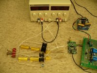
So, I built up one channel using 50W power resistors, and put the mosfets (FQA19N20C) on heatsinks. I used a lab supply for the +/- rails which made adjustments easier.
Sure enough, the higher you go with rail voltage, the better and better performance gets. I'm not talking by a small amount either. I made it up to +/- 75V which gives about 180mA bias current per leg, for a total of 54W dissipation per channel. At this bias level, I was getting -112dB THD+N, and the frequency response was ruler flat out to 80kHz which is as high as I can measure with a 192kHz input.
That kind of performance is phenomenal for a single stage with a pair of mosfets. That's better than most people can do with three $20 op amps and a plethora of supporting circuitry/power supplies. If you have heatsinks, and don't mind owning a DAC that dissipates 100W, then I'd give that setup my full blessing.
I'll post my measurement and some pictures of "The beast" (probably has a record for the world's hottest DAC) later today or tomorrow.
Cheers,
Owen
Hi Guys,
As promised, I have a few things to report from the last couple days of testing. This transconductance thing is tricky, and there's a little more to it than I initially thought. I wrongly assumed that if a mosfet has high TC at higher currents, that it would more likely have higher TC at lower currents. I actually sat down and made a test setup to measure several fets, and here's what I came up with so far:
Using 50mA, and 10V DS, 200 ohm source resistance:
FQA46N15: 0.355 S
IXTQ96N15: 0.276 S
FQA19N20C: 0.397 S
ACD101NDD: 0.216 S
FQA28N15: 0.340 S
IRF1324: 0.297 S
IRF540: 0.357 S
IRF740: 0.258 S
These are just a few that I had on hand which I thought would be interesting, and as you can see, the TC performance at such a low bias current is a complete toss up. There's no trend or other characteristic that helps to predict TC at such low levels.
The clear standout so far, however, is the FQA19N20C as used in Nelson's F5. I matched a pair of these for Vgs along with a pair of the IRF710s, and I'm going to do a head-to-head comparison. That's basically the best in the group against one of the the worst as far as TC goes.
Another fun exercise that I did was to crank up the rail voltage to get higher bias current. It's a neat circuit because you can basically just drop the gate voltage all the way down (adjust the pot to read 0V at the gate) then you can ramp up the rails as high as you want (limited by resistor and FET dissipation) then re-adjust to get the 1.65V at the source and you're off to the races.
So, I built up one channel using 50W power resistors, and put the mosfets (FQA19N20C) on heatsinks. I used a lab supply for the +/- rails which made adjustments easier.
Sure enough, the higher you go with rail voltage, the better and better performance gets. I'm not talking by a small amount either. I made it up to +/- 75V which gives about 180mA bias current per leg, for a total of 54W dissipation per channel. At this bias level, I was getting -112dB THD+N, and the frequency response was ruler flat out to 80kHz which is as high as I can measure with a 192kHz input.
That kind of performance is phenomenal for a single stage with a pair of mosfets. That's better than most people can do with three $20 op amps and a plethora of supporting circuitry/power supplies. If you have heatsinks, and don't mind owning a DAC that dissipates 100W, then I'd give that setup my full blessing.
I'll post my measurement and some pictures of "The beast" (probably has a record for the world's hottest DAC) later today or tomorrow.
Cheers,
Owen
so looks like the 540 still performs rather well, ok i'm gonna give that a whirl in the next few days. will crank up the sigma 22 to +/-50v and finish off my slab-o-copper heatsinks, bolt the lot to them and let her rip. anything else I should be aware of with the buffer in the circuit in these circumstances Owen?
Hi qusp,
If you're going to up the voltage, you'll have to lose the buffer. To be honest, the buffer is really not doing anything for you if you're using the resistance values I suggested. Without the buffer, you've got an output impedance of 200 ohms, and with it you jump to 1k. Not really much of a buffer, so just get rid of it. Cheaper, easier to build, and better performance.
With the higher voltage, you'll have 25V across each jfet and at 10mA that's 0.25 watt's per device which I think is too high for a TO-92 in the long term.
Cheers,
Owen
I'll post my measurement and some pictures of "The beast" (probably has a record for the world's hottest DAC) later today or tomorrow.
Your findings are really cool! Any pictures of the beast yet?
Hi qusp,
If you're going to up the voltage, you'll have to lose the buffer. To be honest, the buffer is really not doing anything for you if you're using the resistance values I suggested. Without the buffer, you've got an output impedance of 200 ohms, and with it you jump to 1k. Not really much of a buffer, so just get rid of it. Cheaper, easier to build, and better performance.
With the higher voltage, you'll have 25V across each jfet and at 10mA that's 0.25 watt's per device which I think is too high for a TO-92 in the long term.
Cheers,
Owen
Owen:
Great project ! Nelson and company have done great things and you are definitely continuing their tradition.
Is post # 61 considered to be without the B1 buffer?
Thanks
Bob
Hi Guys,
Ive got some graphs to post finally, so feel free to take a look below. I also measured several more fets, so here's a re-cap:
FQA46N15: 0.355 S
IXTQ96N15: 0.276 S
FQA19N20C: 0.397 S
ACD101NDD: 0.216 S
FQA28N15: 0.340 S
IRF1324: 0.297 S
IRF540: 0.357 S
IRF740: 0.258 S
IRF640: 0.256 S
IRF510: 0.054 S
IRFP4310Z: 0.374 S
IRF1310: 0.356 S
IRF644: 0.281 S
FQA32N20: 0.419 S
ST75NF20: 0.199 S
ST40NF20: 0.189 S
IRFP3415: 0.395 S
What you can take away from this is that you shouldn't use the IRF510, and that you have a plethora of other choices that are good. Looks like the FQA32N20 is the best of this group at 50mA and 10V DS.
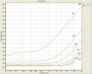
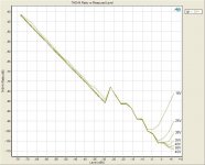
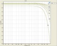
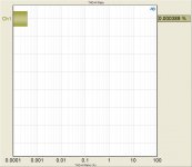
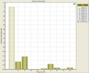
As for the graphs, I used the same circuit, and adjusted the rails to various levels, taking measurements at each step. The voltages were 18V, 25V, 30V, 35V, 40V, 45V, and 50V.
As you can see, things just keep getting better the higher the voltage gets.
Bob:
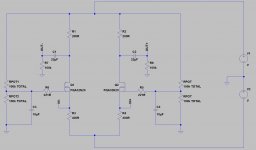
The schematic in post #61 is the non-buffered version, and now that I look back, you should omit the 100k resistor across the two outputs before the cap. I thought it would help with start-up transients, but that turned out to not be a problem.
That's the schematic used in the measurements below, minus two filter caps which need to be adjusted.
qusp:
The IRF540 should be fine for the higher voltage version, just make sure you've got a heatsink. At 50V, the top resistor dissipates about 3.5W, the bottom resistors about 6.5W and the FET will dissipate about 3W.
Cheers,
Owen
Ive got some graphs to post finally, so feel free to take a look below. I also measured several more fets, so here's a re-cap:
FQA46N15: 0.355 S
IXTQ96N15: 0.276 S
FQA19N20C: 0.397 S
ACD101NDD: 0.216 S
FQA28N15: 0.340 S
IRF1324: 0.297 S
IRF540: 0.357 S
IRF740: 0.258 S
IRF640: 0.256 S
IRF510: 0.054 S
IRFP4310Z: 0.374 S
IRF1310: 0.356 S
IRF644: 0.281 S
FQA32N20: 0.419 S
ST75NF20: 0.199 S
ST40NF20: 0.189 S
IRFP3415: 0.395 S
What you can take away from this is that you shouldn't use the IRF510, and that you have a plethora of other choices that are good. Looks like the FQA32N20 is the best of this group at 50mA and 10V DS.
As for the graphs, I used the same circuit, and adjusted the rails to various levels, taking measurements at each step. The voltages were 18V, 25V, 30V, 35V, 40V, 45V, and 50V.
As you can see, things just keep getting better the higher the voltage gets.
Bob:
The schematic in post #61 is the non-buffered version, and now that I look back, you should omit the 100k resistor across the two outputs before the cap. I thought it would help with start-up transients, but that turned out to not be a problem.
That's the schematic used in the measurements below, minus two filter caps which need to be adjusted.
qusp:
The IRF540 should be fine for the higher voltage version, just make sure you've got a heatsink. At 50V, the top resistor dissipates about 3.5W, the bottom resistors about 6.5W and the FET will dissipate about 3W.
Cheers,
Owen
Attachments
qusp:
Since you already have the 500R and 1k resistors, I would just use those. Note that you'll get twice the gain (4VRMS @0dBFS with the Buffalo II). You'll have half the bias current, half the power dissipation, and as a result performance will suffer by a tiny amount.
The only resistors that need to dissipate power are the 200R and 400R resistors. Everything else can be 1/4 watt or smaller. The trimpots used to set the gate voltage will need to be upped to 100K which is what I used.
The 100K resistors from the output to ground will be needed to prevent the leakage in the caps from building up a voltage on your outputs. Make sure to leave them in.
I'm running the circuit without any filter caps at the moment, but I should get around to calculating/testing the correct values in the next few days.
flocchini:
I'm currently revising the boards to allow for heatsinks on the resistors and mosfets, so I should be done sometime nest week.
Cheers,
Owen
so once youve got those values all sorted out I wont need the 100k to ground? isnt that messing with my output impedance? so with your PCB, you are still allowing both through-hole and SMD versions of most things?
I thought as much about the rating resistors, but I was thinking of using 1w to be safe anyway because in the 3 different versions of this circuit I have seen anywhere from 1/4-2W specified on all but the power resistors. so will you have spots for the SMD version (DPAK) of the caddock (MP 725) power resistors? this build will be passed on to a friend and i'll probably grab yours. so you are running without output caps? is it possible to do this all the time if the circuit is well tuned? I would love that.
I thought as much about the rating resistors, but I was thinking of using 1w to be safe anyway because in the 3 different versions of this circuit I have seen anywhere from 1/4-2W specified on all but the power resistors. so will you have spots for the SMD version (DPAK) of the caddock (MP 725) power resistors? this build will be passed on to a friend and i'll probably grab yours. so you are running without output caps? is it possible to do this all the time if the circuit is well tuned? I would love that.
qusp:
Both the output caps and the 100k resistors that follow them are going to be needed no matter what. Even though the differential between those two points would be 0 volts in the perfect circuit, there's still going to be 25 volts between each node and ground, so unless you use a transformer, you'll need to use caps to get rid of that. I explained the need for the 100k resistors above, so unless you always have the circuit connected to a preamp or amp, I would strongly suggest keeping the 100k resistors.
As for the layout, I'll provide both footprints where it is possible. The mosfets will only be through-hole, and I'm leaning towards PTH Caddock resistors for the 200 and 400 ohm parts mounted on heatsinks, but I'll allow for SMD here too for those who want to build the 18 volt version.
I've attached below what I consider to be the bare minimum anyone would want to go with this circuit. There are no filter caps to induce a rolloff, which means you'll get flat output well past 100kHz. Some find this bad, I personally can't tell the difference with or without the caps. The two 100k resistors are actually just there to represent a 100k pot. This arrangement provides less fine adjustment than the other way, but it omits 2 resistors. It also allows you to crank up the gate voltage, which means you can blow your mosfets if you don't start them at a low value. This circuit is exactly what was used to make "The Beast" and it works very well.
Whatever you do, ALWAYS ADJUST THE CIRCUIT WITH THE DAC DISCONNECTED and then readjust once you've connected it. If you're using higher rail voltage, you could end up with a high or low voltage at the source of the fets before you adjust it.
Cheers,
Owen
Attachments
Hi Guys,
Ive got some graphs to post finally, so feel free to take a look below. I also measured several more fets, so here's a re-cap:
FQA46N15: 0.355 S
IXTQ96N15: 0.276 S
FQA19N20C: 0.397 S
ACD101NDD: 0.216 S
FQA28N15: 0.340 S
IRF1324: 0.297 S
IRF540: 0.357 S
IRF740: 0.258 S
IRF640: 0.256 S
IRF510: 0.054 S
IRFP4310Z: 0.374 S
IRF1310: 0.356 S
IRF644: 0.281 S
FQA32N20: 0.419 S
ST75NF20: 0.199 S
ST40NF20: 0.189 S
IRFP3415: 0.395 S
What you can take away from this is that you shouldn't use the IRF510, and that you have a plethora of other choices that are good. Looks like the FQA32N20 is the best of this group at 50mA and 10V DS.
As for the graphs, I used the same circuit, and adjusted the rails to various levels, taking measurements at each step. The voltages were 18V, 25V, 30V, 35V, 40V, 45V, and 50V.
As you can see, things just keep getting better the higher the voltage gets.
Bob:
The schematic in post #61 is the non-buffered version, and now that I look back, you should omit the 100k resistor across the two outputs before the cap. I thought it would help with start-up transients, but that turned out to not be a problem.
That's the schematic used in the measurements below, minus two filter caps which need to be adjusted.
qusp:
The IRF540 should be fine for the higher voltage version, just make sure you've got a heatsink. At 50V, the top resistor dissipates about 3.5W, the bottom resistors about 6.5W and the FET will dissipate about 3W.
Cheers,
Owen
thx for your hard work
which Is the device measured on graphs
Hi Samoloko,
The device in the graphs is the FQA32N20. It's readily available, and has the highest transconductance at 50mA.
At some point I'll re-do the TC testing at 130mA and 25V DS, but that will have to wait for another day. I'm sure the results will be different, but I'm not sure by how much.
Cheers,
Owen
The device in the graphs is the FQA32N20. It's readily available, and has the highest transconductance at 50mA.
At some point I'll re-do the TC testing at 130mA and 25V DS, but that will have to wait for another day. I'm sure the results will be different, but I'm not sure by how much.
Cheers,
Owen
qusp:
Both the output caps and the 100k resistors that follow them are going to be needed no matter what. Even though the differential between those two points would be 0 volts in the perfect circuit, there's still going to be 25 volts between each node and ground, so unless you use a transformer, you'll need to use caps to get rid of that.
right, now i'm with you. for some reason I wasnt thinking about a failure condition, hmm well actually this will be connected directly to a balanced headamp in the same case and the output will be switched by a relay, so perhaps I can put the 100k after the relay so its not in circuit when not needed. and at the moment I am running transformers on the output, so I guess I could omit the caps too if I chose to continue using them
I explained the need for the 100k resistors above, so unless you always have the circuit connected to a preamp or amp, I would strongly suggest keeping the 100k resistors.
got it
As for the layout, I'll provide both footprints where it is possible. The mosfets will only be through-hole, and I'm leaning towards PTH Caddock resistors for the 200 and 400 ohm parts mounted on heatsinks, but I'll allow for SMD here too for those who want to build the 18 volt version.
cool, I just picked some of the 200/400 SMD caddocks in a preemptive strike
")
I've attached below what I consider to be the bare minimum anyone would want to go with this circuit. There are no filter caps to induce a rolloff, which means you'll get flat output well past 100kHz. Some find this bad, I personally can't tell the difference with or without the caps. The two 100k resistors are actually just there to represent a 100k pot.
cool i'll have a look at that. right, so they are representing a pot, I mentioned that before, but had thought you were talking about the other set of 100K
This arrangement provides less fine adjustment than the other way, but it omits 2 resistors. It also allows you to crank up the gate voltage, which means you can blow your mosfets if you don't start them at a low value. This circuit is exactly what was used to make "The Beast" and it works very well.
i'll give it a try, just bought one of those prototyping PCBs like you had in your pic. ELFA has some great ones that have DSUB and IDC connection points at the card edge, so i'll likely make up an umbilical for sensing and power using a HV one I bought, and another that has HV contacts and coaxial mixed in the same DSUB. They are military connectors from amphenol, i'll end up using them in the final build too to keep things neat, if I go with an external power supply and just keep regs local.
the case is quite a decent size, but its getting pretty packed. will get some pics up next week some time. because im testing lots of different things and nothing is permanent as yet, I equipped everything with pin headers and using molex, so the below is no problem, but I will for sure print it out and put it above the bench
Whatever you do, ALWAYS ADJUST THE CIRCUIT WITH THE DAC DISCONNECTED and then readjust once you've connected it. If you're using higher rail voltage, you could end up with a high or low voltage at the source of the fets before you adjust it.
Cheers,
Owen
thanks for your patience mate, I really appreciate it, I know I can get trying some times. cant wait to crank this up and team it with the new headamps (99% done), everything is coming together, will have the ackodac here next week as well, the buff will be going portable
- Status
- This old topic is closed. If you want to reopen this topic, contact a moderator using the "Report Post" button.
- Home
- Source & Line
- Digital Line Level
- A New Take on the Classic Pass Labs D1 with an ESS Dac