Yet another D1 I/V clone
Very interesting thread!
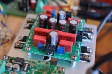
As it turns out, I have been using a D1 I/V stage with an original buffalo DAC for about a year now. Sound is laid back, with layers and layers of detail. It compares favorably to anything I have heard.
As Owen pointed out, new DACs like the ESS swing more current than the PCM63. Referring to the original schematic, I made the following changes to increase bias threefold:
- R26, R33 decreased from 3.3 K to 1 K
- R27, R34 decreased from 1.5 K to 470 ohms
To keep the same cutoff frequencies (RC) for the low pass filters, the following capacitors were adjusted accordingly:
- C40, C45 increased from .01 to .033 uF
- C15, C16 increased from .0027 to .0086 uF
I could not trim the output voltage to 1.65 V without reducing R24, R31 from 100 K to 68 K. The rest of the D1 I/V circuit is stock. Never had the imagination of trying it without the buffer stage. Now I'm curious...
Let me see if I can attach a picture in my next post.
Pierre
Very interesting thread!
As it turns out, I have been using a D1 I/V stage with an original buffalo DAC for about a year now. Sound is laid back, with layers and layers of detail. It compares favorably to anything I have heard.
As Owen pointed out, new DACs like the ESS swing more current than the PCM63. Referring to the original schematic, I made the following changes to increase bias threefold:
- R26, R33 decreased from 3.3 K to 1 K
- R27, R34 decreased from 1.5 K to 470 ohms
To keep the same cutoff frequencies (RC) for the low pass filters, the following capacitors were adjusted accordingly:
- C40, C45 increased from .01 to .033 uF
- C15, C16 increased from .0027 to .0086 uF
I could not trim the output voltage to 1.65 V without reducing R24, R31 from 100 K to 68 K. The rest of the D1 I/V circuit is stock. Never had the imagination of trying it without the buffer stage. Now I'm curious...
Let me see if I can attach a picture in my next post.
Pierre
I hope an image shows up (fingers crossed)...
Pierre
Thanks for your report on modifying an original D1 for the Buffalo DAC!
BTW. Did you make those boards? Got any left?
")
Thanks for your report on modifying an original D1 for the Buffalo DAC!
BTW. Did you make those boards? Got any left?
Yes I made those board, and I have a few left - strictly for DIY use. Send me PM if you are interested. I'll sell below cost. Just glad if they end up playing music instead of gathering dust.
Pierre
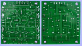
Here's a picture of a naked pcb. Nothing fancy: connect ESS Sabre to input (+IN, -IN), provide power (+30, G, -30), and hook outputs (+M, -M) to XLR connector. You may connect an external volume control (+VOL, -VOL), trim volume with a pot, or skip that portion of this circuit if you prefer. Part numbers match the D1 schematic.
I have a few pcbs left, available on a first come first served basis.
Pierre
I have a few pcbs left, available on a first come first served basis.
Pierre
Attachments
lauret, jkeny, qusp and toufu: you have or will receive PM.
All the others - I regret to say, demand exceeded supply... my spares are gone.
I am prepared to make the files available if somebody wants to organize a group buy for DIY use. Just PM me. Thank you and happy building.
Pierre
All the others - I regret to say, demand exceeded supply... my spares are gone.
I am prepared to make the files available if somebody wants to organize a group buy for DIY use. Just PM me. Thank you and happy building.
Pierre
Pierre , have you experienced any turn-on/off transiant thumps with this setup?
A faint "click" sound at turn on, coming either from the DAC, the I/V or a combination of both. Not enough to warrant a muting circuit in my case. My speakers are medium sensitivity PHL 1340 MTM.
Pierre
pierre, the click is the muting relay on the buffalo
Good to know. Thanks !
pierre, the click is the muting relay on the buffalo
No, that's a Buffalo24 in his setup. There is no output stage and no muting relay on that board.
If you are using balanced signals into and out of the D1 you should get little transient if any. This is because the transient will be almost all common mode. It's only single ended where you could run into problems.
Cheers!
Russ
Last edited:
Russ is right. This is the original Twisted Pear ES9008 board. I like it so much I feel no urge to upgrade this part of my system. At least no yet
The D1 I/V circuit is Nelson Pass's simple, elegant idea of a discrete I/V converter. Thank you, Mr Pass! It is generic and I would not hesitate to mate it with the ES9006, -8, -12, or -16. (Obviously it is not applicable to the voltage output ES9022.)
Running single ended output, there is absolutely no thump at turn on and (perhaps) a very tiny one at turn off. No worries. Of course if you are running balanced, the thing is dead quiet.
Pierre
Running single ended output, there is absolutely no thump at turn on and (perhaps) a very tiny one at turn off. No worries. Of course if you are running balanced, the thing is dead quiet.
Did you mean here single ended output with differential input or single ended input? As in using one balanced board for stereo connection.
Did you mean here single ended output with differential input or single ended input? As in using one balanced board for stereo connection.
I simply listened to the +M output referenced to ground, leaving the balanced input unchanged.
Some have asked about using one balanced board for stereo (e.g. using +in and +M for left channel and -in and -M for right channel). At quick glance, it appears to simply require replacing the differential volume pot and output cap C43 by two pots to ground, and two caps to ground. It looks straightforward (no physical changes to the pcb) and I would expect the circuit and board to work this way.
However, you need a single ended output DAC to go that route. Now note that the ES9008 has differential outputs, and that some well regarded commercial products use single ended output DACs in differential mode. There must be a reason - and I would guess that it helps noise rejection.
In DIY land, all the fun is in trying things and being surprised.
Hoping this helps...
Pierre
PS: I am going to be offline for a couple of days.
For those interested in D1 variants, an older, yet relevant thread with comments from Mr Pass can be found here:
http://www.diyaudio.com/forums/pass-labs/19922-modifying-d1-i-v-stage-x-ccs.html#post231717.
Pierre
http://www.diyaudio.com/forums/pass-labs/19922-modifying-d1-i-v-stage-x-ccs.html#post231717.
Pierre
- Status
- This old topic is closed. If you want to reopen this topic, contact a moderator using the "Report Post" button.
- Home
- Source & Line
- Digital Line Level
- A New Take on the Classic Pass Labs D1 with an ESS Dac