pump and VREG capacitor
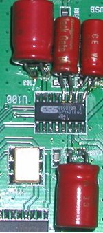
Just replaced with BlackGate N on my audio-widget for PUMP and VREG capacitor first, then +/- supply bypass, sounds pretty good, less harsh and quieter background (using USB power now). ES9023 3.3V is regulated by ADP-151.
Any recommendation over sync/async clock is appreciated.
Just replaced with BlackGate N on my audio-widget for PUMP and VREG capacitor first, then +/- supply bypass, sounds pretty good, less harsh and quieter background (using USB power now). ES9023 3.3V is regulated by ADP-151.
Any recommendation over sync/async clock is appreciated.
Attachments
Last edited:
Just replaced with BlackGate N on my audio-widget for PUMP and VREG capacitor first, then +/- supply bypass <SNIP>
What values for which locations?
TIA!
Greg in Mississippi
Greg, take a look here: http://www.diyaudio.com/forums/digital-source/185761-open-source-usb-interface-audio-widget-8.html
Post #76
Post #76
Another EUVL ES9022 Board commits music!
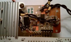
I spent some time over the last week or so getting installing one of Patrick's ES9022 cards into my digital source, with final installation this morning. I'm using a computer playback system based on the cMP formula, but with extensive power supply upgrades (ALL supplies are fully linear including the one powering the computer motherboard).
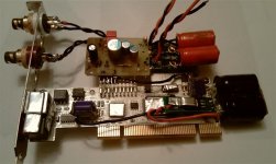
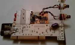
The digital output is via an ESI Juli@ PCI sound card, which has separate digital and analog sections. By removing the analog section, you have access to the I2S lines and can easily connect them to a DAC. In the past, I've mounted other custom DAC cards on Juli@ digital sections including several variations based on the AK4397 & AK4399 DACs along with a Twisted Pear Buffalo32 that I setup for a friend (based on that experience, I have a TP Buffalo-II here waiting for me to find time to implement it).
I modified the Juli@ a bit by upgrading the power supply lines (increased local filter caps plus upgrading the 3.3v regulator that powers most of the digital chips to a Dexa regulator). I also cut the +5v & +/- 12v power feeds on the PCI connector of the card and feed it from separate linear supplies instead of the motherboard power.
The combo of Patrick's card and my modified Juli@ sounded pretty good right away. Now both the sound card and the ES9022 card have run all day and are improving as they warm up and break-in. Sound is now very respectable... definitely in the same region as the highly-tweaked AK4399-based DAC card w/high-current high-speed video buffer output stage that was perched on a Juli@ digital section before... and not far from the Buffalo32.
Attached are a few pictures of the ES9022 card mounted on the Juli@. Patrick's ES9022 card needs a 9v and a 6v input and I feed it from a couple of Dexa as pre-regulators (The raw DC I used for the AK4399 card and it's output stage were +/- 19v & +12v and I needed to knock them down before feeding them to Patrick's board).
I'm pretty impressed and Patrick's card is a great value. Looking over his implementation, I see very few things I might want to upgrade... Mostly I'm interested in trying higher-test regulators to bypass the on-card 1763's. I'll go either with Dexa or small Salas-ish shunts mounted very close to the card & feeding just past the existing regulator outputs. I also may try different output filter caps... maybe AMTRANS boutique-types. Other than that, I'll likely leave it alone... not sure I can otherwise improve on he'd wrought.
I am talking with Patrick on getting a 2nd card to try in Synch mode. The Juli@ digital section has two clocks, 22.5792 MHz (used for 44.1 & it's multiples-sampling rates) and 24.576 MHz (used for 48 & it's multiples). I generally upsample in the computer to 192, so a 49.152 Mhz clock divided down to 24.576 MHz should theoretically work well.
I'll post updates when I get around to either the regulator or synch-mode upgrades.
Greg in Mississippi
I spent some time over the last week or so getting installing one of Patrick's ES9022 cards into my digital source, with final installation this morning. I'm using a computer playback system based on the cMP formula, but with extensive power supply upgrades (ALL supplies are fully linear including the one powering the computer motherboard).
The digital output is via an ESI Juli@ PCI sound card, which has separate digital and analog sections. By removing the analog section, you have access to the I2S lines and can easily connect them to a DAC. In the past, I've mounted other custom DAC cards on Juli@ digital sections including several variations based on the AK4397 & AK4399 DACs along with a Twisted Pear Buffalo32 that I setup for a friend (based on that experience, I have a TP Buffalo-II here waiting for me to find time to implement it).
I modified the Juli@ a bit by upgrading the power supply lines (increased local filter caps plus upgrading the 3.3v regulator that powers most of the digital chips to a Dexa regulator). I also cut the +5v & +/- 12v power feeds on the PCI connector of the card and feed it from separate linear supplies instead of the motherboard power.
The combo of Patrick's card and my modified Juli@ sounded pretty good right away. Now both the sound card and the ES9022 card have run all day and are improving as they warm up and break-in. Sound is now very respectable... definitely in the same region as the highly-tweaked AK4399-based DAC card w/high-current high-speed video buffer output stage that was perched on a Juli@ digital section before... and not far from the Buffalo32.
Attached are a few pictures of the ES9022 card mounted on the Juli@. Patrick's ES9022 card needs a 9v and a 6v input and I feed it from a couple of Dexa as pre-regulators (The raw DC I used for the AK4399 card and it's output stage were +/- 19v & +12v and I needed to knock them down before feeding them to Patrick's board).
I'm pretty impressed and Patrick's card is a great value. Looking over his implementation, I see very few things I might want to upgrade... Mostly I'm interested in trying higher-test regulators to bypass the on-card 1763's. I'll go either with Dexa or small Salas-ish shunts mounted very close to the card & feeding just past the existing regulator outputs. I also may try different output filter caps... maybe AMTRANS boutique-types. Other than that, I'll likely leave it alone... not sure I can otherwise improve on he'd wrought.
I am talking with Patrick on getting a 2nd card to try in Synch mode. The Juli@ digital section has two clocks, 22.5792 MHz (used for 44.1 & it's multiples-sampling rates) and 24.576 MHz (used for 48 & it's multiples). I generally upsample in the computer to 192, so a 49.152 Mhz clock divided down to 24.576 MHz should theoretically work well.
I'll post updates when I get around to either the regulator or synch-mode upgrades.
Greg in Mississippi
Attachments
P.S. Massimo, I forgot to say 'THANKS!' for the link. That post answered my questions entirely... and I may try upgrading those caps after doing my regulator upgrades.
P.P.S. I also forgot to say that powering the Juli@ separate from the motherboard power and upgrading the on-board regulators made a very significant difference in sound quality when I did that a couple of years ago. The AK4358 DAC on the analog section did very well and it took a couple of iterations of my AK4397/AK4399 implementations to truly best it. I suspect that bypassing the mixing and output stages on the analog section might allow it to keep pace with the newer DACs in most areas of performance... that's a 'someday when I get time' project.
Greg in Mississippi
Attachments
A different application of the ES9023
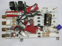
There has been a lot of interest using the 9022/23 with SD players and lately PCs. I wanted to see what could be made of it for a more generic conventional DAC that supports 44.1 to 192KHz rates for use with CD and SACD transports as well as perhaps a PC.
I started it a year ago with no time to finish. The layout has been sitting around for three or four months waiting for some time so I finally finished up and built one...
It uses the Wolfsen 8804 receiver in hardware mode and the 9023 with a DCB1 type follower configured as a second order low pass filter. I added the follower because I intend to drive a stepped attenuator or low value pot directly into a headphone amp for an all battery powered version later on. EUVL suggested the Bessel, so I made accommodation for both a simple datasheet first order filter with a buffer as well as the second order filter. Thanks Patrick as I believe it sounds better with it...
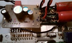
As you can see it is mostly SMT. I stayed away from ceramics except for the 12MHz crystal load caps (NPO types). Bulk caps are SP series Panasonic and the bypass and others are Panasonic SMT film. You can pretty much glean everything else you might want to know from the picture. Not anywhere near the least expensive way to go, but we do this for our own enjoyment so we can make these nth degree choices with a clear conscience, right?
The power supply behind the DAC is a line supply with filtering and follower type pre-regs to minimize noise and improve the line rejection of the DAC regulators at higher frequencies. Not as quiet as bateries, but getting closer... I will build another one of these for battery power with this part lopped off for use with the head amp later on.
Highly recommended for those brave enough to try. It sounds great!

Dave
There has been a lot of interest using the 9022/23 with SD players and lately PCs. I wanted to see what could be made of it for a more generic conventional DAC that supports 44.1 to 192KHz rates for use with CD and SACD transports as well as perhaps a PC.
I started it a year ago with no time to finish. The layout has been sitting around for three or four months waiting for some time so I finally finished up and built one...
It uses the Wolfsen 8804 receiver in hardware mode and the 9023 with a DCB1 type follower configured as a second order low pass filter. I added the follower because I intend to drive a stepped attenuator or low value pot directly into a headphone amp for an all battery powered version later on. EUVL suggested the Bessel, so I made accommodation for both a simple datasheet first order filter with a buffer as well as the second order filter. Thanks Patrick as I believe it sounds better with it...
As you can see it is mostly SMT. I stayed away from ceramics except for the 12MHz crystal load caps (NPO types). Bulk caps are SP series Panasonic and the bypass and others are Panasonic SMT film. You can pretty much glean everything else you might want to know from the picture. Not anywhere near the least expensive way to go, but we do this for our own enjoyment so we can make these nth degree choices with a clear conscience, right?
The power supply behind the DAC is a line supply with filtering and follower type pre-regs to minimize noise and improve the line rejection of the DAC regulators at higher frequencies. Not as quiet as bateries, but getting closer... I will build another one of these for battery power with this part lopped off for use with the head amp later on.
Highly recommended for those brave enough to try. It sounds great!
Dave
Attachments
Hi Patrick,
>One XO for both ? What freq ?
No, 50MHz XO for the 9023 and a 12MHz crystal for the 8804. In hardware mode this makes it useful from 44.1 to 192KHz (minus 176.4K of course). Having the elastic buffer 8804 is beneficial here over a CS part in my opinion even though the 9023 has good rejection.
I have a different XO coming to try once available as well. 30-40% lower phase noise throughout the spectrum. May not make one bit of difference but I want to try.
>LSK389 for the DCB1 ?
Yes. I'm using it at 14 volts across the pair and want to experiment with higher and lower voltages to see if there is a sweet spot. I also want to change the cutoff as I think the datasheet values' frequency makes it just a tad bright compared to a 9018. The DCB1 LPF should make this easier to do without adding noticeable distortion...
Dave
> Yes. I'm using it at 14 volts across the pair
I use 18 (+/-9V). Also handy with batteries.
> The DCB1 LPF should make this easier to do without adding noticeable distortion...
You can also do that (vary freq) by changing the output shunt caps without the Bessel.
The difference is that it will always be first order.
Rest see email.
Patrick
I use 18 (+/-9V). Also handy with batteries.
> The DCB1 LPF should make this easier to do without adding noticeable distortion...
You can also do that (vary freq) by changing the output shunt caps without the Bessel.
The difference is that it will always be first order.
Rest see email.
Patrick
TheShaman,
It depends on how you feel about 0805 and sot23-5 sized SMT components?
I only made a few PCBs. I also made a couple of minor recto-cranial mistakes in the power supply section so the current PCB requires some cuts and jumps. Not bad for Rev A. The DAC is in pretty good shape though aside from some additions for the 9023.
There is still quite a bit of testing I want to do yet. If I make the corrections to the power supply and the additions necessary for the 9023 in a revisied layout, I'll consider it.
One other correction - I called it a Bessel low pass filter in the original post with the picture. It is actually sallen-key LPF circuit topology with some modifications of the values. It was too late after a long day I suppose...
Dave
> It depends on how you feel about 0805 and sot23-5 sized SMT components?
In my WM8804 modules, there are 2 0402 MLCC's, hand soldered right at the pins of the 8804.
")
> It is actually sallen-key LPF circuit
You can configure a Sallen Key to a Bessel or Butterworth or else by choosing the right values for R's and C's.
Patrick
In my WM8804 modules, there are 2 0402 MLCC's, hand soldered right at the pins of the 8804.
> It is actually sallen-key LPF circuit
You can configure a Sallen Key to a Bessel or Butterworth or else by choosing the right values for R's and C's.
Patrick
Hi Patrick,
"In my WM8804 modules, there are 2 0402 MLCC's, hand soldered right at the pins of the 8804."
I refer to 0402 components as salt and pepper because they are just about the size of course ground seasoning! Try hand building a processor prototype with five or six hundred of them... I think it was management's way of making sure I knew what I was getting everybody into.
"You can configure a Sallen Key to a Bessel or Butterworth or else by choosing the right values for R's and C's"
Between the circuit shelving and the final shape it really doesnt exactly fit any of them... BTW I have a really cool fix for the shelving if you are interested. I did not use it here as I did not see the need. I have other plans for it...
TheShawman,
"I'm only 30 years old and I think I should take advantage of my good eyesight while it lasts."
Definitely, use it while you can. It only gets tougher to see!
I'll let you know.
Dave
Last edited:
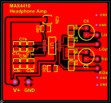
MAX4410 Headphone Amp for ES9022/23
Hello,
I made a ES9022/23 prototype with WM8804 receiver a while ago. I posted the pictures of the PCB in the forum earlier.
I wanted to have a simple headphone amp for it and decided to give a try with MAX4410, mainly because it can run on +3.3v which kind of simplified the power requirements.
Its a small board of size 1.4 x 1.4 inches. I used the reference schematic from MAX4410 datasheet. Its all SMT except for the input capacitors which I did not have any SMTs on hand so went with through the hole parts.
C1x and C3x caps have three 0805 pads to play with different cap values, R1-R4 are 10K, C2x are for power supply filters, C4-C5 are input caps.
Its a single sided board and I etched it at home. I added a ALPS pot between the output of ES9022 and the headphone amp inputs for volume control. Listening to it right now as I am posting this message. Sounds pretty good driving my Audio Technica M50s.
Here is the pic of the PCB.
__________________________________________________________
Subbu
Attachments
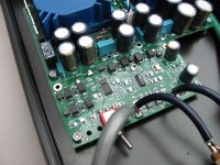
For those interested, I want to share some insight and suggested improvements to the 9022/23 circuit that might be beneficial to others building these.
There is some residual ~1.5 MHz noise from the built in negative supply generator. It is on the order of 125uV in my layout. None of this noise shows up on the output but it can back radiate into other circuits on board so it is a good idea to do the following:
*Power the 9022/23 with its own supply.
*Power the 9022/23 clock oscillator with its own supply, or at least a supply separate from the 9023.
*Connect the XO through a trace directly to the 9023. Don't use a series termination resistor (The 9023 likes a fast rise time in my layout).
*Power the SPDIF receiver/I2S source with its own supply, or at least a supply separate from the 9023.
*Add low impedance bypass caps as close as possible (if not directly across) the AVCC, VREG, and NEG pins to ground.
Patrick suggested additional bulk capacitance on the supplies to the 9023. This is a very good addition. I added it only to the VREG supply as it made the residual noise slightly worse when added to the AVCC and NEG pins. My just be my layout so try it and see what you like.
*Add good polymer bulk capacitance to the VREG near the pin, 100uF to 560uF range is worth trying.
Output noise at zero volts is ~15uV on each channel and the distortion at 1V RMS is <0.005%. Not bad for a 2 dollar chip and around a hundred dollars worth of parts... I added $75 or so for the low noise line supplies and $60 for an enclosure. You could do it with batteries and a plank of wood.
Dave
Last edited:
Interesting tips, thank you for sharing.
Suggested parts and value for AVCC & NEG pins to gnd caps?
*Add low impedance bypass caps as close as possible (if not directly across) the AVCC, VREG, and NEG pins to ground.
Suggested parts and value for AVCC & NEG pins to gnd caps?
Massimo,
Here is an old post from Patrick with some details of his implementation. The 0603 MLCC cap he suggested a few posts above is a 2.2uF X7R. Looks like the NEG cap is directy on top of the legs of the 9022. The AVCC cap is further away by physical necessity.
I am using film caps and still experimenting to see if they can be made to work reasonably well...
Dave
- Status
- This old topic is closed. If you want to reopen this topic, contact a moderator using the "Report Post" button.
- Home
- Source & Line
- Digital Line Level
- Anybody using the new ESS Vout DAC (ES9022)?