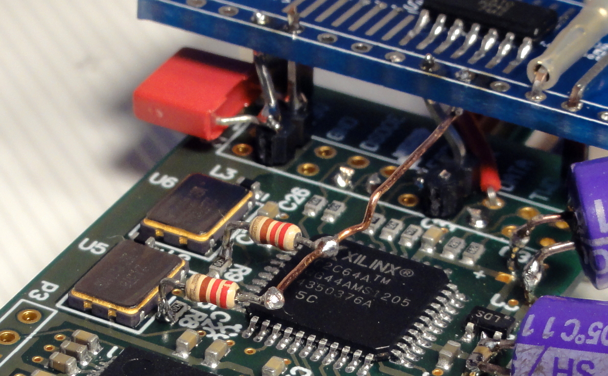
a much better solution as I see it (but not very elegant) in case of the amanero is to take the MCLK directly from the 2 onboard XO's tied together because they are selected independently and they are not both ON at the same time (it depends on what material you listen to from the 44 and 48k family when they are internally selected)
it's just like GLT has done it at hifiduino, but without necessarily using reclocking, so tie together the 2 XO outputs using two 39 0hm resistor from their outputs and then a piece of wire to tie them together which will go directly to the ES9023/22 MCLK input, and it will work in synchronous mode and will also avoid the added jitter of the amanero's MCU to the MCLK
Amanero USB Synchronous Reclocking | H i F i D U I N O
I hadn't read this thread until now and I think that my post to the group buy of J.G Filter/Buffer wasn't to the right place.
I put it here with a quote and I' m very sorry for this fault.
I put it here with a quote and I' m very sorry for this fault.
Hi to all member. I hope so to post it to the right place...
I have completed the board some time ago and the last days I have some measurements about this.
At first I am not familiar with this design and my theory electronic background isn't big.
I saw that this filter-buffer raise the upper acoustic frequencies from the 5KHz step by step with the almost 0.25dB at 24KHz and so up over the 50KHz.
Here is an ARTA capture with 96KHz sampling (it is from the headphone output of an EMU-0404 + buffer)

As I know, this filter designed from J.G for the 9022-9023 Sabre dac-chips. If I measured right by ARTA the output of 9023 (after the filter), the following capture demonstrate the comparison between the 9023 direct output via direct output + J.G filter/buffer (the black is from 9023 direct output). The AD captured done by analogue inputs of EMU-0404 (usb).
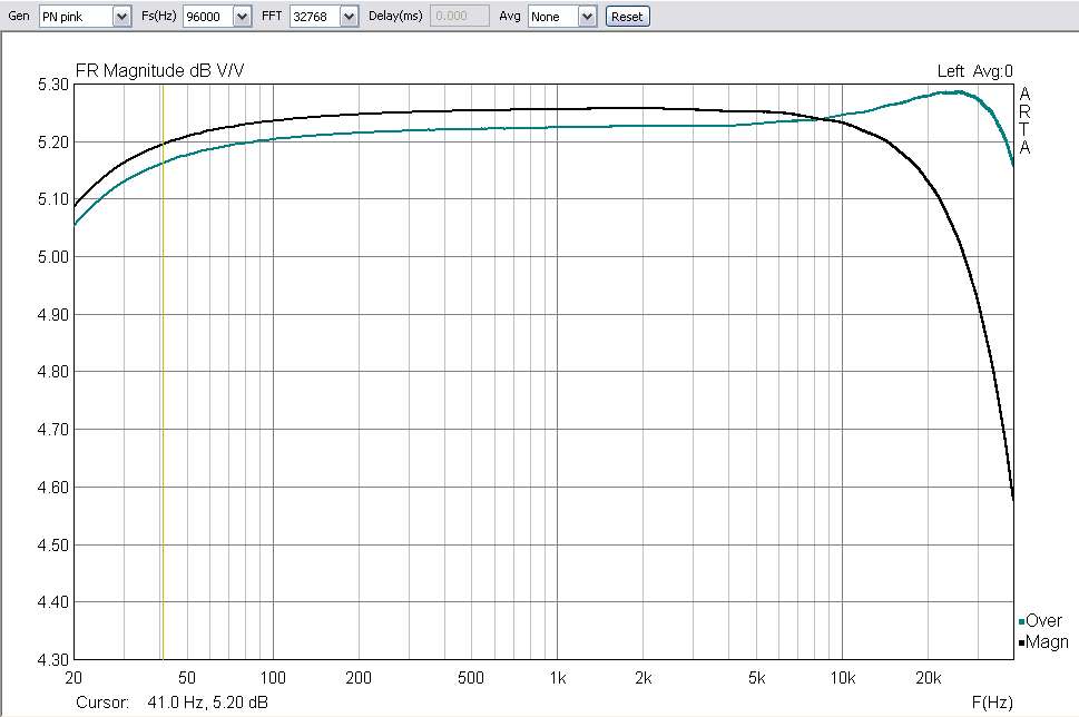
The upper raise of frequency response is clearly. I don't know if this is a choice by designer or not.
The same seems with the square wave of 20KHz.
Here, the output of Hameg generator was calibrated to 2Vrms (1KHz sinewave) and then a square wave achieved at the same level as before. The signal was driven to buffer input and the output of buffer was driven to oscilloscope for capturing through Pomona 50 Ohm resistor termination.
There is an overshooting, probably normal cause the upper lift of frequencies.
I observed that if the signal was closer to 2.87Vrms (with reference to 1KHz sinewave) the captured square was almost perfect.

Sorry for my english...I would like the opinion of more experienced members with this design.
What if I use a ceramic dis cap instead of a pp film cap. Does it do more harm than good?
If you use COG ceramic than it is OK. COG have very low distortion (film is still a tad better but not that much). Do NOT use X7R, X5R,...
regards, Daniel
If you use COG ceramic than it is OK. COG have very low distortion (film is still a tad better but not that much). Do NOT use X7R, X5R,...
regards, Daniel
Thanks for the advice. This is my bad not to read. I found what Patrick recommended for this position. I'd go for the FKP.
The following quote is from the link:http://www.diyaudio.com/forums/grou...hard-filter-buffer-es9022-71.html#post3814153 post #707
Joachim many thanks for the reply to my question. As I said to this thread, I ask sorry for all members that I hadn't read it before. For that reason I upload my message to GB of the EUVL board. Sorry again.
Because the output of 9022 dac-chip is the same with the 9023 dac-chip, is my measurement (look at post #585) after the filter of 9023 dac output according to that you said at the message #317 (I have attach it below).
As I said before, I see that this filter lifts the upper frequencies step by step from 5KHz and more.
Is that according to your design or I have done measurement fault?
The filter-buffer was designed for an ESS EUVL DAC.
That DAC already has a passive output filter with a capacitor so the design was done with that cap as part of the filter.
Joachim many thanks for the reply to my question. As I said to this thread, I ask sorry for all members that I hadn't read it before. For that reason I upload my message to GB of the EUVL board. Sorry again.
Because the output of 9022 dac-chip is the same with the 9023 dac-chip, is my measurement (look at post #585) after the filter of 9023 dac output according to that you said at the message #317 (I have attach it below).
As I said before, I see that this filter lifts the upper frequencies step by step from 5KHz and more.
Is that according to your design or I have done measurement fault?
This buffer is very wide band. When you simulate it at very high frequencies ( actually the layout and the PCB plays a role too ) you will see that there is a peak, then a minimum and then again the response can co up. This is because first the circuit goes inductive and then capacitive again. I like to stay out of that region. Also the input capacitance of a Fet is not very linear. I fact it is a very bad capacitor with distortion. The cascoding reduces that effect somewhat. You can use an NPO ceramic. That works well too. It is basically an open circuit in the audible range.
Last edited:
Powering the EUVL Buffer for ES9023
Hello,
Have little questions please as it seems than batteries are approved unanimously :
Which smd regulators (or not) should we use with batteries for both rails of the EUVL Buffer (matched Fets) ? 15 Volts out from the regs ? Do I Need a more complex design (shunt regulator with voltage ref à la TL431 on both rails for a symetric +/- V. out?)
Best (and cheaper?) Batteries are LiFePo or simples little lead batteries for motorbikes could match it ?
About the 220 uf caps of the BOM, could Nichicon KZ muse be a better choice than 220 uf Panasonic FC ?
thank you (read the entire thread but was not able to abstract by myself a shematic about a PS for the Buffer )
)
Hello,
Have little questions please as it seems than batteries are approved unanimously :
Which smd regulators (or not) should we use with batteries for both rails of the EUVL Buffer (matched Fets) ? 15 Volts out from the regs ? Do I Need a more complex design (shunt regulator with voltage ref à la TL431 on both rails for a symetric +/- V. out?)
Best (and cheaper?) Batteries are LiFePo or simples little lead batteries for motorbikes could match it ?
About the 220 uf caps of the BOM, could Nichicon KZ muse be a better choice than 220 uf Panasonic FC ?
thank you (read the entire thread but was not able to abstract by myself a shematic about a PS for the Buffer
)Maybe everyone already found this, i searched for the patent number here on diyaudio but could not find any posts that contained it. This is what i found when searching for an AES paper:
Patent US8350734 - Method and apparatus for digital to analog conversion of data stream with ... - Google Patents
It seems to outline how the jitter-rejection of the ESS Sabre chips work. An interesting read to say the least.
Seems the engineers over at ESS where at least in part influenced by the paper i was looking for, "Plug and Play? An Investigation into problems and solutions of digital audio networks" by Frandsen & Lave.
I've got a question about the ES9023 dac and I figured this would be the best place to post.
I have an ES9023 / PCM2706 DAC. The Dac output is way too loud for me and I want to decrease it.
While looking at the ES9023 datasheet I noticed the resistor referred to as R8.
According to the datasheet, it is used to adjust the output level and thus prevent clipping at different supply voltages. The datasheet also mentions adjustable output level as a feature.
I took a look at the board and it uses a Micrel 5205 3.3V and a 130kOhm R8 value, which is suggested for a 3.6V supply on the datasheet. This apparently limits it to 2.0Vrms.
Now the real question: Could I just lower R8 to significantly reduce the output level? If yes, do I need to replace other components? (I don't think so.) What R8 value should I try? / What is realistic?
Something like 1/4 of the current volume level is roughly what I'm looking for.
Thanks for your help!
I've connected it to a O2 headphone amplifier. The amp is already set to unity gain. With my 40 Ohm headphones I have like 15° of useable (heavily unbalanced) volume control.
Does it really have such an effect on the sound? Should I just use resistors as a "volume control" on the output of the dac or is there something else I could do?
Does it really have such an effect on the sound? Should I just use resistors as a "volume control" on the output of the dac or is there something else I could do?
Last edited:
I've connected it to a O2 headphone amplifier. The amp is already set to unity gain. With my 40 Ohm headphones I have like 15° of useable (heavily unbalanced) volume control.
Does it really have such an effect on the sound? Should I just use resistors as a "volume control" on the output of the dac or is there something else I could do?
Jean-Paul is correct. I was disappointed with the effect adding any resistance in place for R8. Always sounded worse.
You would be better off doing the level reduction somewhere else, perhaps at the pot in the amplifier...
Dave
At the pot in the amp isn't really an option in this case so I probably need to do it at the output of the dac/input of the amp.
What resistance would be best on the output of the Dac? 5K? 10K?
I just tried IN-10Kohm-OUT- 100ohm-GND and although the increase in volume when turning the pot has decreased, I still find myself using very little of the pot's range.
What resistance would be best on the output of the Dac? 5K? 10K?
I just tried IN-10Kohm-OUT- 100ohm-GND and although the increase in volume when turning the pot has decreased, I still find myself using very little of the pot's range.
At the pot in the amp isn't really an option in this case
Why ? It is the most logical thing to do. Please explain. A series resistor per channel is a rudimentary but effective solution.
Are you sure you have unity gain ?
Why ? It is the most logical thing to do. Please explain. A series resistor per channel is a rudimentary but effective solution.
Are you sure you have unity gain ?
I must admit I'm not testing it with the O2 because I sold one of my O2's and the other one can't assembled until I get my soldering iron fixed.
I tried it with another amp, which -just like the O2- is set to unity gain.
The O2 consists of input - gain stage - volume control - output stage - output
Of course I could cut some traces on the O2 board and solder in resistors but that would also attentuate the external input, which I want to keep (unattentuated). Ideally I would use a switch to switch the attentuation on/off.
Would adding a second, fixed "volume control" at the O2's input be a worse solution? How much of a compromise is this anyway?
- Status
- This old topic is closed. If you want to reopen this topic, contact a moderator using the "Report Post" button.
- Home
- Source & Line
- Digital Line Level
- Anybody using the new ESS Vout DAC (ES9022)?