I'm splitting this off from a very interesting thread that started about a cheap but good DAC board from China & possible ways to mod it. It later got into a very interesting discussion about the use of transformers on voltage out DACs such as the CS4398, or the PCM1793 as used in my Musiland Monitor 01 US DAC. (I have one of the new Vout Sabre DACs ordered so I'll be trying trafos on this & an original Sabre32 also)
I have to thank Bill Fuss for introducing the use of transformers on these DACs and although I know it's not an original idea by him, I can't see much treatment of it on this forum - hence the new thread")
Now let me start with the good news (my questions later) - the sound of this arrangement is excellent - natural & dynamic without strain. Compared to the op-amp output stage it's much more life-like. This is my first time to do such an output stage so I'm not speaking as an expert here, by any means, and I still have a lot of experimentation to do but the sound does depend on the trafo used. I tried 2 different trafos - a small cheap encapsulated Talema mains toroidal 16VA 115-0-115:22-0-22 just for my first trial & it sounded good but when I put on my second trafo which is a Dave Slagle made 1:1 nickel based (don't know the %) it showed up the Talema - much more high end clarity & a bit more low end bass as well. These trafos weren't made for this role so they were very much an experiment but have prompted me to ordering a Sescom line output trafo from eBay.
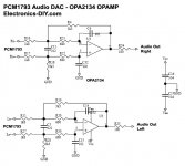
Here's my existing output stage schematic attached - a differential Vout from a PCM1793 into a LPF with gain of 1.83 to bring the level up to 2 Vrms. Instead of OPA2134 my board has an inferior op-amp OP275 but it still sounded good stock. I moved the 1K8 R on each leg down to the cap so as it was now isolated from the DAC output & I could connect a wire to each vacated solder pad on the DAC output side. I will be able to use a switch or jumper to reconnect the original output stage if needed.
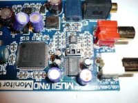
(Pic of board is attached before this mod)
I'm running this into an unmodded Lepai Tripath TA2020 amp (which is down for modding shortly)
So now my questions:
- I believe this should work purely differentially into the amp without a ground from the DAC board but just using one side of the trafo differential out as the ground but I get music and lots of hum in this arrangement. Any ideas why?
- I can get it to work beautifully, with using a ground connection to the DAC & one of the trafo differential out wires as the signal, no hum.
- When connected this way I have an unconnected trafo differential out wire - if I put a 100R across this & the ground I get a louder & more rich sound - what's happening here?
I have to thank Bill Fuss for introducing the use of transformers on these DACs and although I know it's not an original idea by him, I can't see much treatment of it on this forum - hence the new thread
Now let me start with the good news (my questions later) - the sound of this arrangement is excellent - natural & dynamic without strain. Compared to the op-amp output stage it's much more life-like. This is my first time to do such an output stage so I'm not speaking as an expert here, by any means, and I still have a lot of experimentation to do but the sound does depend on the trafo used. I tried 2 different trafos - a small cheap encapsulated Talema mains toroidal 16VA 115-0-115:22-0-22 just for my first trial & it sounded good but when I put on my second trafo which is a Dave Slagle made 1:1 nickel based (don't know the %) it showed up the Talema - much more high end clarity & a bit more low end bass as well. These trafos weren't made for this role so they were very much an experiment but have prompted me to ordering a Sescom line output trafo from eBay.
Here's my existing output stage schematic attached - a differential Vout from a PCM1793 into a LPF with gain of 1.83 to bring the level up to 2 Vrms. Instead of OPA2134 my board has an inferior op-amp OP275 but it still sounded good stock. I moved the 1K8 R on each leg down to the cap so as it was now isolated from the DAC output & I could connect a wire to each vacated solder pad on the DAC output side. I will be able to use a switch or jumper to reconnect the original output stage if needed.
(Pic of board is attached before this mod)
I'm running this into an unmodded Lepai Tripath TA2020 amp (which is down for modding shortly)
So now my questions:
- I believe this should work purely differentially into the amp without a ground from the DAC board but just using one side of the trafo differential out as the ground but I get music and lots of hum in this arrangement. Any ideas why?
- I can get it to work beautifully, with using a ground connection to the DAC & one of the trafo differential out wires as the signal, no hum.
- When connected this way I have an unconnected trafo differential out wire - if I put a 100R across this & the ground I get a louder & more rich sound - what's happening here?
Attachments
You will this site has lots of useful info., incl. transformers and DAC quality.
http://www.audiodesignguide.com/DAC_final/DacFinal.html
I am interested in the transformers as well, I would be interested in alternative trans. to those from Lundahl which are very expensive.
http://www.audiodesignguide.com/DAC_final/DacFinal.html
I am interested in the transformers as well, I would be interested in alternative trans. to those from Lundahl which are very expensive.
Welcome to the wonderful world of transformer DACs! I've been doing this a lot and really love it. Most good differential output DACs respond well to this mod. No opamps or LPFs needed.
Yes, the transformer quality matters. I've tested many, they all sound different. High nickel content is good. I have mine custom made by BudP, they are the best.
I know what you mean about the hum. Sometimes I can get away without connecting the low point of the secondary to ground, but mostly not.
Tweaking your load resistor will give different results, but many circuits are not too picky about about it.
You can also use a transformer as the DC blocker on your Tripath input. Just tie the low point of the secondary to the 2.5V supply instead of ground. Works great, no cap needed. Have fun!
Thanks ttan98 - I did see that site before but I'll read it again in the light of new info
Speaking of which - did you leave Maui? Why, it's so idyllic 
Is the water warm?Welcome to the wonderful world of transformer DACs!
Speaking of which - did you leave Maui? Why, it's so idyllic One thing - if the DAC chip datasheet states the output min impedance is 1K8 (as the PCM1793 does) should this not be the series R on each leg? And if doing this then putting a cap to ground after this to give a LPF is probably not going to do any harm or is it? It's all new to me & I'm tying to learn the principles/vagaries of this. However, I did build the second channel last night without any LPF and initial impressions are that it sounds the same as the other channel with 1K8+ 1nF LPF (88KHz) - so I'm not sure what gives - the transformers windings measure 200R on each leg?I've been doing this a lot and really love it. Most good differential output DACs respond well to this mod. No opamps or LPFs needed.
Can you give any ranking to known transformers that you've used? The thing that usually puts people off trafo use is their cost - I had this Dave Slagle one here which I used but had I only tested it with the cheap Talema, I would not have been so impressed. I'm sure that BudP's are excellent and well worth it (as are Dave Slagle's) but there are some cheaper options for use in this role that I've picked up on like UTC, Sescom, maybe Triad? which seem to offer good bang/buck? Can you give us your experience from your tests?Yes, the transformer quality matters. I've tested many, they all sound different. High nickel content is good. I have mine custom made by BudP, they are the best.
So any explanation to this? In my existing config, I have left one of the secondary legs unconnected & just used the other one as the hot lead & ground from the DAC as the feed into the amp.I know what you mean about the hum. Sometimes I can get away without connecting the low point of the secondary to ground, but mostly not.
Is that what I'm doing with the 100R across the above unconnected secondary lead & gnd? What does this do & is there a way to test this to find the optimum. I have a scope (but haven't used it much)!Tweaking your load resistor will give different results, but many circuits are not too picky about about it.
Cool, I hadn't thought of this one - I had already posted asking about ways to DC connect a TDA1543 to a Tripath but this is goodYou can also use a transformer as the DC blocker on your Tripath input. Just tie the low point of the secondary to the 2.5V supply instead of ground. Works great, no cap needed. Have fun!
One thing that occurs to me on re-reading your post - you mention the low side of the secondary a couple of times, I thought it didn't matter which side of the secondary was thought of as the hot signal lead although by rights to keep phase correct, it should be the high side used. Have I just answered my own question?
On the Tripath DC blocker connection, I'm a bit concerned as I bring the ground from the DAC straight through (bypassing the trafo) & connect it to the low-side of the secondary. If I now tie the biascap pin directly to this low-side which has 2.5V pin it, will this not feed back to the DCA ground and damage the DAC?
On the Tripath DC blocker connection, I'm a bit concerned as I bring the ground from the DAC straight through (bypassing the trafo) & connect it to the low-side of the secondary. If I now tie the biascap pin directly to this low-side which has 2.5V pin it, will this not feed back to the DCA ground and damage the DAC?
Well let me see if I can answer.
Hope that helped!
Yes, Maui no more. I was in the art biz, got hit early and hard by the economic storm.- did you leave Maui? Why, it's so idyllic
No, it's the minimum impedance the DAC wants to work into. That will always be higher than the DCR of the primary. It is a combo of the DCR, inductance and the load reflected back from the secondary. At high frequencies it can rise quite high. With most 1:1 transformers I've measured - about 2.5K across the primary will look like a fairly flat 1K load to the DAC (~10K to 100K on the secondary).One thing - if the DAC chip datasheet states the output min impedance is 1K8 (as the PCM1793 does) should this not be the series R on each leg?
Prolly not. But I don't think you need it. The transformer will clean up most of it anyway.And if doing this then putting a cap to ground after this to give a LPF is probably not going to do any harm or is it?
Of the many I've tested I would rate Onetics (BudP) the highest. All the good points of the others with none of the bad. Jensen next. Very nice. Maybe some various Chinese stuff, then Edcor (cheap!). Last for me was Sowter, I just didn't like them. Still need to test Cinemag and maybe Neutrik. But I from what I know about them, I doubt they will best the Jensens.Can you give any ranking to known transformers that you've used?
Don't forget size and weight. Can be a real pain.The thing that usually puts people off trafo use is their cost
I don't understand.So any explanation to this? In my existing config, I have left one of the secondary legs unconnected & just used the other one as the hot lead & ground from the DAC as the feed into the amp.
I just meant the "negative pole." It's all relative.One thing that occurs to me on re-reading your post - you mention the low side of the secondary a couple of times
Hope that helped!
Sorry to to hear thatYes, Maui no more. I was in the art biz, got hit early and hard by the economic storm.
I measure the resistance across each primary as 200R - it's a dual so 400R in total. Is this the DCR?No, it's the minimum impedance the DAC wants to work into. That will always be higher than the DCR of the primary. It is a combo of the DCR, inductance and the load reflected back from the secondary. At high frequencies it can rise quite high. With most 1:1 transformers I've measured - about 2.5K across the primary will look like a fairly flat 1K load to the DAC (~10K to 100K on the secondary).
Thanks for this - I'd expect BudP's to be expensive & the Jensens are not cheap either. I bought the Sescom's MI-97 for $50 a pair on a recommendaton - I'll post how they sound when I get them!Of the many I've tested I would rate Onetics (BudP) the highest. All the good points of the others with none of the bad. Jensen next. Very nice. Maybe some various Chinese stuff, then Edcor (cheap!). Last for me was Sowter, I just didn't like them. Still need to test Cinemag and maybe Neutrik. But I from what I know about them, I doubt they will best the Jensens.
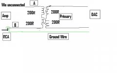
I've attached a crude drawing which I hope explains it. One of my secondary leads is left unconnected (A) to the amp - I just use the other one (B) as the signal into the centre pin of RCA connector & a ground wire runs all the way back to the DAC board. Is this wrong? It seems to be the only way it will work? If I connect both legs without ground I get hum. I discovered that if I connect the A wire across a 100R to ground I get a higher volume (stronger signal) - any explanation for this?I don't understand.
That is why I had pause about the Tripath connection - should I connect the A wire to the Biascap, this will give a 2.5V bias to the B wire but also 2.5V to the ground because of the 100R across it to ground - should I leave out this 100R?
It sure did & I'm sorry for all the questions - it's just that transformers are another world to me in this role & there doesn't seem to be much info on here - thanks for your helpHope that helped!
I really don't know how to calculate the R reflected back from the secondaries & is this R the impedance of the input stage of the amp? Why does my cross-connected 100R increase the volume?Attachments
Last edited:
A few answers:
Your circuit will work, I've done it (by accident.) But it's not the best way to do it. And you will often see 2X the output wired like this. You should really connect one end of the secondary to the point where the input cap normally goes. The other end to the 2.5V bias. Think of the 2.5V bias as your ground.
If your transformer has dual windings then you have the ability of wiring them in series or parallel. That will change the ratio of the transformer - and the DCR, as you note. In series is probably best for you. So 400R. With that you have to figure in the inductance of the transfo and the load on the other side. With a 1:1 transformer the reflected load is the same as the secondary load. Thus 1:1
The impedance curve of the transformer will start at DCR at DC (of course) and rise rapidly toward about 20Hz. From there it will rise more with a few kinks and bumps to be a bit higher than the secondary load at 20KHz. As you can imagine, putting a 2K or 3K resistor across this will swamp that rise. You'll get a much flatter curve and your chip will be happier.
Sounds like you got a great deal on your Sescom. The Jensens I used are about $35 each. Still a bargain, I think. Let us know how they sound!
I'm sorry Mike, I don't understand - can you do a quick sketch please? Also I don't just want to make this specific to a Tripath amp as I may want to plug it into other amps!
Also you say a 2k to 3K across - do you mean across the secondary or across one secondary & ground? See my diagram
Have you heard the Sescoms? How do you rate them?
Also you say a 2k to 3K across - do you mean across the secondary or across one secondary & ground? See my diagram
Have you heard the Sescoms? How do you rate them?
Attachments
Last edited:
See Behringer 2496DCX threads
Replacing the output section with a transformer is a great idea.
See the Behringer 2496DCX threads for a great deal of information that is relevant. It also uses a voltage DAC.
Just a few points. The DAC will need to see some resistance. Without enough load it will try to draw current and this can lead to some problems. Check the manufacturers specs. For instance the AKM used in the Behringer needs to see at least 600-1000 ohm load. This resistor of course can be part of the LPF (RC filter) necessary for the DACs reconstruction filter. If the DAC has a balanced output and you need an unbalanced output, the transformer also makes this an ideal element in the circuit for eliminating the DC that the two signals ride on. BTW, a properly chosen transformer can provide some additional LPF.
The trick is choosing the "right" transformer. They will vary in sound quality and they will vary wildly in price. In terms of price, from high to low the choices can include Lundahl, Sowter, Jensen, Cinemag, Edcor. If you are unfamiliar with transformers, read the tutorial on the Jensen Website.
Good Luck
Thanks WithTarragon,
I thought the DAC needed to see resistance - for PCM1793 min R is 1K8 but I built one channel with 1K8 (as part of LPF) in each differential leg to the primary windings & I built one channel with no series Rs just straight out to the primary - both sound the same. So I'm confused as the DCR of the 1:1 trafo I'm using is 400R (primary) & 400R (secondary).
I'm not sure what you mean by "right" transformer - is there not a quality ranking or are we talking about the dreaded & elusive "synergy" curse?
I just got some of the new Sabre Vout DAcs in the post (ES9022), so I'll be trying the transformers with these as well
Here is a little diagram. The top is for a normal amp hook up. You would just plug this into an integrated amp or a preamp.
The bottom is cap-less connection to a T-Amp. But - you will have no analog volume control. OK if you do it digitally. But if you need a normal volume pot you'll need another transformer. A TVC would be ideal here. (not the autoformer type).
The bottom is cap-less connection to a T-Amp. But - you will have no analog volume control. OK if you do it digitally. But if you need a normal volume pot you'll need another transformer. A TVC would be ideal here. (not the autoformer type).
Attachments
Hi John and Everyone,
I wasn't the first in the other thread to try trafos, but I might have been the person that did the most research, and I have previous trafo experience with concert sound equipment going back more years than I would like to admit.
It's funny that the casual practice you have shown of tying a ground to a trafo primary or secondary is totally contradictory to the original need for their use in the first place, galvanic isolation.
John, your trafos are definitely not line out units if they measure 400 DCR, the nominal impedance is in the range of 10x to 20x the measured DCR so they are around 5k/5k. In your wiring diagram with one leg floating they are acting as coupling capacitors, not trafos. With a 5k trafo, try a 5k load across the secondary. Contrary to many opinions, 600ohm output trafos do not need a load. Look it up if you don't believe me.
I know nothing about T-Amps, but I know not to subject trafos to DC, it will magnetize the cores unless there is an air gap built into them. The only air gapped trafo I tried was the UTC A-22 which was fine sounding but missing a lot of low end weight.
That's my two cents, best, Bill.
Contrary to many opinions, 600ohm output trafos do not need a load. Look it up if you don't believe me.
And the times I have tried to point this out have been met with more naysayers than supporters. It appears to be mainly centered around a belief that transmission line theory applies for 20 - 20 kHz audio. So whether you are talking about a 10k:600 ohm transformer or a cat5 with its 100 ohm characteristic impedance, adding resistance/load is the better way to go.
Not sure how this belief continues to propagate among DIY enthusiasts, but they believe it very strongly.
I'm a bit confused.
What exactly is the goal here? To simply transformer couple the output of a PCM1793?
Steve, I guess it's what you state but also to apply LPF bandwidth limiting, DC de-coupling & convert Bal to SE without using Capacitors or OP- amps? Is there a better way? I have seen discussions on the Buffalo DAC thread about using a transformer as one of the best output stages. I also see Wavelength using transformer outputs on their Sabre implementation. These rae the motivations why I tried it. I also had a good Dave Slagle pre-amp trafo here which allowed me to experiment without shelling out for a decent transformer to try this out & I'm impressed.
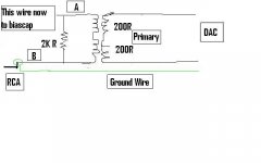
Panomaniac, (Mike, isn't it?) - thanks for the diagram - I see now
So I've attached my version which is different in the red circled area which just leaves one leg of the secondary floating (although now connected a 100R across this leg & ground). I'll experiment further trying to understand what's going on.I see your 2nd Tripath diagram - I can see how the connection to biascap floats the signal at the 2.5V needed but I'm not sure how it will work without a ground - I will give it a go, thank you
Attachments
Hi John and Everyone,
I wasn't the first in the other thread to try trafos, but I might have been the person that did the most research, and I have previous trafo experience with concert sound equipment going back more years than I would like to admit.
It's funny that the casual practice you have shown of tying a ground to a trafo primary or secondary is totally contradictory to the original need for their use in the first place, galvanic isolation.
John, your trafos are definitely not line out units if they measure 400 DCR, the nominal impedance is in the range of 10x to 20x the measured DCR so they are around 5k/5k. In your wiring diagram with one leg floating they are acting as coupling capacitors, not trafos. With a 5k trafo, try a 5k load across the secondary. Contrary to many opinions, 600ohm output trafos do not need a load. Look it up if you don't believe me.
I know nothing about T-Amps, but I know not to subject trafos to DC, it will magnetize the cores unless there is an air gap built into them. The only air gapped trafo I tried was the UTC A-22 which was fine sounding but missing a lot of low end weight.
That's my two cents, best, Bill.
Thanks Bill,
If I understand you correctly, I measured the resistance across the Primary as 400ohm DCR. The impedance is 10X to 20X this, so 4K to 8K?
Bill, I wasn't being casual about this. I had these transformers here & I decided to experiment with them & was just trying to get it to work without hum & this is how I found it to work but as I said all along, and why I started this thread, was to try understand what's going on & how to do this correctly. Of course, I lost the galvanic isolation along the way - is this the main benefit you see in using the transformer approach?
Here's what Dave Slagle said about these transformers
And the transformers are bifilar woundDCR per winding 200 ohms (400r end to end)
inductance per winding 130hy (520H end to end)
DC offset possible 1ma
10V@20hz gives you 3500 gauss (with ~7Kgauss being saturation for 80% nickel)
Driven from a 600R balanced source with a 13K resistor across each secondary and signal taken from CT to + i get bandwidth past 400K with the occasional wiggle of less than half a dB above the audio band.
dropping the load resistors to 500 ohms each gives a few dB peak at say 125K
Bill, the Tripath use of the transformer does not put DC through the coil, or does it?
About the load needed on Transformers here's what Slagle says, for what it's worth:
Indeed transformers should be terminated on one side or the other with a low impedance otherwise the finite inductance will get you. I did come to the realization that since the bifilars do not like to be loaded, you could put your 10K (or whatever) load resistor across the primary with the same net results. (i think). The transformers will not need a load in order to behave so maybe the primary is the way to do it?? This is the same approach i have been taking lately with phono SUT's that often want to see more of a load than we like to present to iron that behaves properly in the first place. I have always found loading to hurt the sound of iron but sometimes it is unavoidable.
Last edited:
Thanks Bill,
If I understand you correctly, I measured the resistance across the Primary as 400ohm DCR. The impedance is 10X to 20X this, so 4K to 8K?
Bill, I wasn't being casual about this. I had these transformers here & I decided to experiment with them & was just trying to get it to work without hum & this is how I found it to work but as I said all along, and why I started this thread, was to try understand what's going on & how to do this correctly. Of course, I lost the galvanic isolation along the way - is this the main benefit you see in using the transformer approach?
Here's what Dave Slagle said about these transformers And the transformers are bifilar wound
Bill, the Tripath use of the transformer does not put DC through the coil, or does it?
About the load needed on Transformers here's what Slagle says, for what it's worth:
Hi John,
I completely understand your outlook, and that additional info from the designer is helpful, but you must be careful about the terms high impedance vs low impedance. In SS eqpmnt 5k is high, in tube stuff 5k is low.
The nominal impedance is generally the design parameter but does not reflect the value the source will see, that is directly reflected through the trafo from the secondary load to the source. Apparently the trafo likes a 10k load but your amp would see a 5k source impedance, possibly too high, don't know.
Getting back to basics, the designer has stated his source as 600ohms balanced which is in the ballpark of your dac chip output. The secondaries should be totally isolated from the dac board. If there is hum you might try grounding the ct of the primaries to the dac board, but I have never had to.
The basic wiring concept is simple, balanced out from the chip to balanced in on the trafo to either balanced or unbalanced out of the trafo. No grounds except for a needed reference ground for your downstream single ended equipment which is simply tying one side of the secondary to the shield of the RCAs and not the chassis. I have used both balanced and SE preamps with zero hum.
If the Tripath needs something else then you have some research to do. Try the basic setup on a different amp to gain some insight, if the Tripath is problematic.
If you are using a meter to verify the circuit output and have no signal as previously stated in the other thread then you have problems other than the trafo implementation. I don't mean to be denegrating in my statements, I just tend toward bluntness, a fault I have always had.
Best regards, Bill
Good point about the diff between SS Vs Tube. As I said these Slagle trafos were what I had at hand & just had a try with them - maybe they're not suited but the sound from them was excellent in my drawn configuration, even if they were only operating as capacitors. (I'll try capacitor output separately as an experiment)Hi John,
I completely understand your outlook, and that additional info from the designer is helpful, but you must be careful about the terms high impedance vs low impedance. In SS eqpmnt 5k is high, in tube stuff 5k is low.
The nominal impedance is generally the design parameter but does not reflect the value the source will see, that is directly reflected through the trafo from the secondary load to the source. Apparently the trafo likes a 10k load but your amp would see a 5k source impedance, possibly too high, don't know.
I'll try grounding the primary CT.Getting back to basics, the designer has stated his source as 600ohms balanced which is in the ballpark of your dac chip output. The secondaries should be totally isolated from the dac board. If there is hum you might try grounding the ct of the primaries to the dac board, but I have never had to.
This is the way I would also have understood trafos to work, that is before I actually tried it & got hum,no signal, etc. This threw me & I realised that I needed some expert help!The basic wiring concept is simple, balanced out from the chip to balanced in on the trafo to either balanced or unbalanced out of the trafo. No grounds except for a needed reference ground for your downstream single ended equipment which is simply tying one side of the secondary to the shield of the RCAs and not the chassis. I have used both balanced and SE preamps with zero hum.
It's just that the Tripath has 2.5V bias on it's inputs (It's a Class D amp) which is normally blocked by a capacitor - Panomaniac was suggesting a way to avoid using a capacitor by the schematic he drew.If the Tripath needs something else then you have some research to do. Try the basic setup on a different amp to gain some insight, if the Tripath is problematic.
No I now have signal but with the configuration I drew. Time for some more experimentsIf you are using a meter to verify the circuit output and have no signal as previously stated in the other thread then you have problems other than the trafo implementation.
I like bluntness - it's unequivocal! There's too much double speak, spin & unclear communication around today, it's refreshing to get direct answers to questions - thank you!I don't mean to be denegrating in my statements, I just tend toward bluntness, a fault I have always had.
Best regards, John
I see your 2nd Tripath diagram - I can see how the connection to biascap floats the signal at the 2.5V needed but I'm not sure how it will work without a ground - I will give it a go, thank you
I agree with Bill. The bottom diagram by panomaniac (post 13) should work without hum.
If you have hum them either something isn't hooked up right or you have a power supply fault. Or a bad transformer.
I say that without knowing what the amp input schematic looks like. Do you have a link to it?
isolating the grounds is the main benefit you will see in using this transformer approach. You shouldn't need to connect grounds between the DAC and amp.
- Status
- This old topic is closed. If you want to reopen this topic, contact a moderator using the "Report Post" button.
- Home
- Source & Line
- Digital Line Level
- DAC ouput using Transformer