I have a DAC chip with differential voltage output to drive a D class chip with differential voltage inputs.
Now i need to find a way how to properly attenuate the differential signal with digital pots to provide volume control.
So whats the easiest proper way to get volume control on such a analog signal.
(oh and sorry for such a dumb question)
Now i need to find a way how to properly attenuate the differential signal with digital pots to provide volume control.
So whats the easiest proper way to get volume control on such a analog signal.
(oh and sorry for such a dumb question)
Well i was hoping for also some kind of linear control on it.Because i had the idea to be able to limit the amp down to a certain power (Setting the linear control to 1/2 would turn the 240W per channel in to 120W per channel)
I like to avoid digital attenuation in the DSP chip thats driving the DAC because it causes loss of bit depth.
I like to avoid digital attenuation in the DSP chip thats driving the DAC because it causes loss of bit depth.
If you're using it as a volume control, you don't want linear. See
http://sound.westhost.com/project01.htm
Also, you can't "turn down" the maximum power of an amplifier, it has a fixed gain. The max power would strictly be determined by the maximum DAC output and the power amp gain.
Finally, reducing the gain by half would reduce the power by one-quarter.
What are you really trying to do with this control? Volume control or speaker protection?
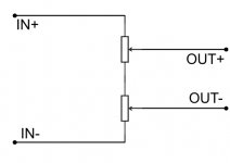
Okey after some tough and a few simulations i figured out that this configuration should work for linearly controlling the output power.If the puts used here are log and there high side connected in the middle (reverse of what such a pot should be used)
Do you guys agree with my theory?
Do you guys agree with my theory?
Attachments
The design Andrew gave would be the best to use and has the advantage of only needing a single gang pot. With careful selection of series resistor and pot values, your desired halfway setting could give 10dB attenuation (half power). I have done this for an unbalanced line before.
I would think it depends on how critical of sound quality one desires, but really have not explored this part yet. Some old Wireless World articles talked a lot about impedance matching.Well Andrews idea was for normal volume control.To get power control i need the exact opposite.Turn a log pot around so its fast on the beginning rather the end as this makes the output power linear with the pot setting.
Oh and is matching resistances that important?
...
I like to avoid digital attenuation in the DSP chip thats driving the DAC because it causes loss of bit depth.
not likely true with Delta-Sigma DACs, many have differential linearity far below the analog output noise floor - much less than the noise floor of any real world recording - and the DACs digital attenuation should track much better than any analog solution
I didn't recommend tying the 'ground' end of the pots to ground so I don't think that's correct. To see why, feed identical signals to the two signal ends of the pots to emulate common mode interference. Since no current flows through the pots the voltage drop across any two points is zero, no matter where you tap off to feed the differential input.twin pots will ruin the balance of the impedances.
Okey i did some spice simulation on this differential signal impedance thing. And it is true putting different value resistors on each leg introduces interference in the signal, but its not as critical as it seams. 1K of mismatch between them caused 0,11dB of the 6dB ground noise to bleed in to the signal.
So yeah it is true that non matching impedances cause noise to get in but even at a 1K difference the noise that got in is very tiny, in my opinion too tiny to worry about.The DAC and amp are in the same case so ground shouldn't be very noisy.(Amp also has a analog ground)
So yeah it is true that non matching impedances cause noise to get in but even at a 1K difference the noise that got in is very tiny, in my opinion too tiny to worry about.The DAC and amp are in the same case so ground shouldn't be very noisy.(Amp also has a analog ground)
Well the simulation has shown that the noise that comes in to the signal is not dependant of the % of difference between the impedances but by the value its off.This is because 1K and 2K on the differential line has the same noise as 10K and 11K.
This again is impacted by the amplifiers input impedance.(My chip has 33K) The higher the impedance of the amps inputs are the more difference is alowed on the impedance of the differential lines.
So in the end it all comes down to what you have on the end of the differential line.Lower its impedance the less tolerable it is to impedance differences between the two differential lines.At leats that whats SwictherCAD IV has shown.
Bernie, go and read Jung and Self.
0.1% error reduces the interference rejection of a balanced feed. 1% error massively reduces it.
Yes, true. At 1% difference between the two source impedances limits your common mode noise and hum reduction to max 40dB. At 10% imbalance, a puny 20dB.
It's the difference ratio that determines the cancellation, not the value, although the value as such does of course impact the noise generation.
Bottom line: use lowest value resistors that you can handle, and then make them match.
There's a lot of this material on the web when you google for instance 'Bill Whitlock'
")
jd
- Status
- This old topic is closed. If you want to reopen this topic, contact a moderator using the "Report Post" button.
- Home
- Source & Line
- Digital Line Level
- Volume control of a differential signal