I'm playing around with a TDA1543 DAC & thinking of connecting it to a Tripath TA2024 amp. Now before I blow up everything I wanted to get some opinion on whether this idea is stupid, fanciful or might work?
The TDA1543 outputs are biased to something like 3V so a capacitor is put on the O/P to block this DC. The TA2024 has something like 2.5V DC on it's input so a cap is used here to block DC from feeding back to anything connected to it's input. You see where I'm going with this, don't you?
Can the TDA DAC be DC connected to the Tripath amp? No caps in the signal path in theory should be better sounding? Could this work somehow? Has anybody gone here before?
I did not try and temping as it looks it seems not doable
The 2,5 Volt is the Bias voltage generated inside the chip amp as mid voltage for the opamp input stage
If you do not decouple DC at the input, the Opamp will see, lets say, 3 Volt
Meaning with a gain of 12 you will have an output of 0,5 * 12 = 6 Volt DC at the output. not so nice for your speakers plus the amplifier clips
but at least you can choose One couple C only if it goes in one chassis
Dear Jkeny,
I did something liek this before. I can't quite remember the full details of the circuit off hand.
I wanted to minimize the op-amp signal has to go through, so I used the op-amp of the TA2022 as the I-V stage. The key is to let only the AC through. That way you save on an I-V stage.
http://diyparadise.com/web/index.php?option=com_content&task=view&id=67&Itemid=26
The difficulty was the volume control. I think i placed a small VR in series about 1 kohm from the output, so it is the same as the resistor to DC on the actual circuit. I also reduced the resistor of the negative feedback loop of the tripath op-amp stage significantly. So it just behaves like an I-V stage. The VR + resistor to DC serves as a current divider, between I-V and virtual ground for the AC. So when the resistance is low, you would get a most of the AC current to the I-V.
I don't think PC remote control is a good one, it just reduces the resolution of the music by reducing the number of bits....
Oon
I don't know what op-amp you mean?oon_the_kid said:I wanted to minimize the op-amp signal has to go through, so I used the op-amp of the TA2022 as the I-V stage. The key is to let only the AC through. That way you save on an I-V stage.
This reminds me that diyparadise have announced that their TA2020 amp (Charlize?) now has no cap on the input! How do they do this? I don't see a schematic.
I'm not really following you here - can you post a rough & ready drawing?The difficulty was the volume control. I think i placed a small VR in series about 1 kohm from the output, so it is the same as the resistor to DC on the actual circuit. I also reduced the resistor of the negative feedback loop of the tripath op-amp stage significantly. So it just behaves like an I-V stage. The VR + resistor to DC serves as a current divider, between I-V and virtual ground for the AC. So when the resistance is low, you would get a most of the AC current to the I-V.
I agree but it depends on whether you have the bits to throw away? I was just giving revintage all vol control options!I don't think PC remote control is a good one, it just reduces the resolution of the music by reducing the number of bits....
Hi Jkeny,
As you know TDA 1543 is an current sink DAC. So you would need an op-amp for an I-V stage first unless you are using a resistor as I-V. Alternatively there are discrete I-V stage. I am using the op-amp stage on the TA2022 as the I-V stage.
I I can't draw a circuit out now, but might scrible it on a piece of paper and scan it in later.
Oon
jkeny said:
I agree but it depends on whether you have the bits to throw away? I was just giving revintage all vol control options!
with a tda1543

once someone should measure DNL of that chip, what philips kindly decided not to publish. Bad DNL means aharmonics,similar to data correlated jitter. Then you 'd see its nowhere near 16bits.
oon_the_kid said:BTW jkeny, what are you using for the I-V converter of the TDA1543 at the moment....
Oon
I'm just completing a TAS1020B USB streamer and will be using it to connect I2S to various DACs, TDA1543, TDA1387(TDA1545 that takes I2S input), Sabre32.
I'm planning a modular build so I can try different options including some of the ideas that have cropped up here: n/c vref pin 7 of TDA1543, slowing & bandwith limiting I2S signal, I2S signal bias adjustment
I'm hoping to try different I/V stages, resistor, Transformer, OPA660 transconductance op-amp, D1, others
Feeding into balanced & SE preamps/amps - Zeus, Baby Huey, SKA, Tripath, others
TAS1020 is finished so initially I wanted to get something working quickly with TDA1543/TDA1545 or TDA1387 ; resistor IV & Tripath amp.
I was interested in how to achieve this before the forum went for a revamp - since found out that in a normal set-up the source ground can be connected to the biascap pin 14 as long as the PS is floating (ie PS ground is not connected to source gnd).
But how could this be made to work in this case when the DAC has 3.3V on it's O/P?
So, Oon, can you scribble down something but I'll be using a resistor for IV as per ec-designs schematic.
Revintage, what was your idea?
But how could this be made to work in this case when the DAC has 3.3V on it's O/P?
So, Oon, can you scribble down something but I'll be using a resistor for IV as per ec-designs schematic.
Revintage, what was your idea?
Last edited:
Hey jkeny,
Scrapped the idea when I realized one should have a volumecontrol between them. Anyway the idea was very simple, just a pot instead of I/V resistor and the wiper set to give zero offset at 2024 output. Otherwise transformer input at the 2024 could be a way to go.
Scrapped the idea when I realized one should have a volumecontrol between them. Anyway the idea was very simple, just a pot instead of I/V resistor and the wiper set to give zero offset at 2024 output. Otherwise transformer input at the 2024 could be a way to go.
This brings up an idea (but it's a half baked one) - I always wondered what about using an Silonex LDR as an IV/Vol control - one of the theories about it's performance being the sonically superior material that makes up it's resistive element (CdS?) - I wonder how they compare to something like a naked bulk Vishay resistor?
These suggestions of an IV vol control brought it back to me & I thought that the galvanic isolation that an LDR affords could do some good here but how might it be used? I can't figure it out but greater minds might?
These suggestions of an IV vol control brought it back to me & I thought that the galvanic isolation that an LDR affords could do some good here but how might it be used? I can't figure it out but greater minds might?
Okay,
What I did is in the circuit.
In this circuit the ratio of the AC current between the 2 resistors is given by the ratio of the resistor between the two of them. So the volume cannot go completely to 0. I can't remember the full details between them. I think I used a 1Kohm for the VR and 100 ohm for R1.
In that way you can reduce the number of stages in between the D to A to the amp, by using the inverting stage of the amp as the I-V itself.
Oon
Attachments
Thanks oon,
I see on the diagram you have a cap on the Tripath input, so it's not DC between the DAC & amp? You have combined IV & vol control though, however, I was hoping to avoid op-amp IV and use a R IV with CC source/sink bias. Is this what you have in use - how does it sound?
I guess a transformer might be the answer but would it tolerate DC on it's primary & on it's secondary without distorting the AC signal?
Attachments
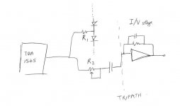
No its not DC. The capacitor prevents DC from going through allowing only the AC part.
My concept was to reduce as many stages as possible.
So by doing this I planned it to have IV in the tripath, replacing the IV, volume pot, and tripath op -amp stage in one. After all inverting op-amp circuit is basically current based anyway. I don't see why one should convert current to voltage to current again.
I must caution you on the use of transformer though, not sure if the DAC likes to see a strong inductor at the input.
Do you have a circuit for the passive I-V circuit? One of their drawbacks is the very low level.you can't get it to fluctuate too much, the DAC was pretty much designed with a constant voltage at the output in mind.
Oon
- Status
- This old topic is closed. If you want to reopen this topic, contact a moderator using the "Report Post" button.
- Home
- Source & Line
- Digital Line Level
- TDA1543 DC connect to TA2024 amp