Thanks Acko. A good read and great timing for me. This literally stopped me in my tracks on purchasing $200 worth of Elma stepped attenuators directly connected to RCA connectors to give a dual mono inline passive volume control setup to be directly connect to my power amp with no preamp.
I think the $200 is better spent on a better DAC that handles onboard digital volume control. It looks like ES9023 is the only DAC chip from ESS that doesn't have onboard volume control. For anyone considering a passive preamp setup, ESS digital volume might be a good option. You can also pre-attenuate the output from the DAC to match your amp's input sensitivity.
Cheers.
Hello guys,
Is there anyone who successfully connected Acko DAC with GLT's Hifidunio code? I have been successful in driving Bufalo II, but now I am ready to switch to Acko DAC with 9012 chip. Here is my Bufalo implementation:
Search Results AR2 H i F i D U I N O
Is there anyone who successfully connected Acko DAC with GLT's Hifidunio code? I have been successful in driving Bufalo II, but now I am ready to switch to Acko DAC with 9012 chip. Here is my Bufalo implementation:
Search Results AR2 H i F i D U I N O
Thank you GLT. Yes I am aware of that post on your site, but I need to know if any hardware or code was adjusted or changed, comparing to regular use with Bufalo II. At least I know it is done, so it is possible. Now I need to figure out how. I contacted that guy, so hopefully I will find out. I am also using, per your recommendation, converter from 5 to 3.2 V for I2C line so that should be fine.
Best
AR2
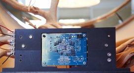
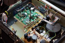
Just to post update here - finally I was able to complete my ACKO's DAC, after such a long line of mishaps solely due to my dumbness and sloppiness. With that it is really worth saying BIG thank you to Acko, from whom I have received an unprecedented support and help. I am still trying to finish all other parts in case and will post more pictures later. For now, here is the idea that someone might like and use. I used Delrin, a plastic material geared for machining purpose to house all the parts - DAC and regs closest possible to each other, and also to be able to have a shortest I2S leads to other electronics I have in the case. Yes I could do it in Aluminum as well, but I liked the durability and easy machining of this plastic. It is very strong that allowed me to tap threads in it, even the small one 6/32. Originally this concept was meant to house two sets of regs and two DACs, one on each side, but for now I am moving forward only with one set. It will be mounted as you see in vertical position. The black plastic base is only for the purpose of holding it during assembly.
I was able to connect to HIFIDUNIO code without any adjustments, and it worked with no problems. In my set up I have LightHarmonics USB to I2S board, Ian's FIFO board with dual clock and Acko's DAC with ESS9012 run in synchronous mode. The only part so far that I am aware is I have to figureout frequency readout, since for dual clock board I still have to receive Crystek 957 clocks, and my HIFIDUNIO board is still set for Bufalo II. I will deal with it when I am done with everything. First hardware, than software... I will update you with pictures when all is packed in case.
I was able to connect to HIFIDUNIO code without any adjustments, and it worked with no problems. In my set up I have LightHarmonics USB to I2S board, Ian's FIFO board with dual clock and Acko's DAC with ESS9012 run in synchronous mode. The only part so far that I am aware is I have to figureout frequency readout, since for dual clock board I still have to receive Crystek 957 clocks, and my HIFIDUNIO board is still set for Bufalo II. I will deal with it when I am done with everything. First hardware, than software... I will update you with pictures when all is packed in case.
Attachments
I was able to connect to HIFIDUNIO code without any adjustments, and it worked with no problems. In my set up I have LightHarmonics USB to I2S board, Ian's FIFO board with dual clock and Acko's DAC with ESS9012 run in synchronous mode. The only part so far that I am aware is I have to figureout frequency readout, since for dual clock board I still have to receive Crystek 957 clocks, and my HIFIDUNIO board is still set for Bufalo II. I will deal with it when I am done with everything. First hardware, than software... I will update you with pictures when all is packed in case.
I read from another poster that in Synchronous mode, the DPLL "doesn't know what to do" so the frequency value in the register is "all over". So in synchronous mode, the source clock must tell the Arduino controller what the sample frequency is. Ian is preparing a serial communication protocol for is Si570 clock board that will have such feature.
Nice setup!
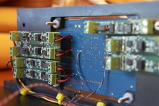
Are those black capacitors high value tantalum caps?
they are the same polymer caps used throughout the ackodac stuff. lowest Z on the market afaik. the Panasonic SP-Cap (Special Polymer)
looking good AR2! one thing though mate, make sure you dont make the analogue current output connections too long so you can have short i2s connections. I wopuld hazard a gues that a few cm extra w.fl cable will damage the sound less than a few cm extra twisted pair analogue cable
looking good AR2! one thing though mate, make sure you dont make the analogue current output connections too long so you can have short i2s connections. I wopuld hazard a gues that a few cm extra w.fl cable will damage the sound less than a few cm extra twisted pair analogue cable
Last edited:
I'd be tempted to twist all of the power supply leads together too ... as in each pair twisted together rather than all running parallel like they are at the moment.
Otherwise that looks really, really nice! Given me some ideas about the next iteration of my case layout too.
Otherwise that looks really, really nice! Given me some ideas about the next iteration of my case layout too.
I read from another poster that in Synchronous mode, the DPLL "doesn't know what to do" so the frequency value in the register is "all over". So in synchronous mode, the source clock must tell the Arduino controller what the sample frequency is. Ian is preparing a serial communication protocol for is Si570 clock board that will have such feature.
Nice setup!
Are those black capacitors high value tantalum caps?
GLT, that is correct, I noticed the same. Although I was thinking it is because in my Hifidunio code I have set 100 MHz for the clock speed, and clocks on Fifio board are just the ones Ian provided for testing - 22.... and 24.... MHz So I am glad to hear that new clock board will solve that so that Hifidunio will again provide a full functionality. As for the capacitors, Qusp gave answer. I would just add they are very good, but also very sensitive and easily damaged.
they are the same polymer caps used throughout the ackodac stuff. lowest Z on the market afaik. the Panasonic SP-Cap (Special Polymer)
looking good AR2! one thing though mate, make sure you dont make the analogue current output connections too long so you can have short i2s connections. I wopuld hazard a gues that a few cm extra w.fl cable will damage the sound less than a few cm extra twisted pair analogue cable
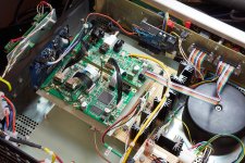
Thank you for suggestion Qusp. What I did not show in these shots is that on the regulator side of the board, where two longer 6/32 screws are sticking out, that is where Legato I/V board is going just slightly above the regulators. That is why those screws are long. It is parallel to the DAC board, which also provides minimum distance between the two boards. Twisted wires shown in the shoot I left at that moment longer, because Legato was not installed yet, but when I finished I shortened them to the shortest possible length. That is the beauty of this mechanical design that everything is very close to each other. My I2S W.FL wires are 60mm each. And MCKL U.FL as well. Analog wires are about that as well. When I am done I will post complete pictures. I did a lots of thinking and several iterations of the design. This configuration works perfect for dual mono, only for that regulators are on the front of DACs, and two DACs are back to back. Still it gives the smallest footprint. Also added benefit is with Legato board, that has resistors that are operating with fairly high temperature. In vertical position, they are above transistors on the board and close to the top, which provides maximum cooling.
I'd be tempted to twist all of the power supply leads together too ... as in each pair twisted together rather than all running parallel like they are at the moment.
Otherwise that looks really, really nice! Given me some ideas about the next iteration of my case layout too.
I am glad if you could find my work helpful. It is not easy packing it all together and closest to each other. Thank you for the suggestion regarding wires, and sure makes all the sense
they are the same polymer caps used throughout the ackodac stuff. lowest Z on the market afaik. the Panasonic SP-Cap (Special Polymer)
looking good AR2! one thing though mate, make sure you dont make the analogue current output connections too long so you can have short i2s connections. I wopuld hazard a gues that a few cm extra w.fl cable will damage the sound less than a few cm extra twisted pair analogue cable
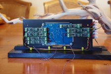
Here is the implementation of whole DAC board and I/V stage.
Attachments
excellent! a little beyond what the makers of that case had in mind i'm sure")
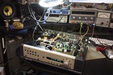
Hehehe, it is way better than what was in. Although, mechanically, it is a great design. The top and side cover is one heavy piece and it slides in through the rails on the side. Just two screws from the rear tighten two stops so that cover cannot slide back and that is it. One of the best designs I have seen.
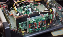
In order to avoid to be redundant, and yet to provide readers of both threads with final pictures, here you will find images of the completed project, and some more info on evolvement of I/O, buffer boards and crossover.
http://www.diyaudio.com/forums/digi...imate-weapon-fight-jitter-29.html#post3238224
and some more info on evolvement of I/O, buffer boards and crossover.
http://www.diyaudio.com/forums/digi...imate-weapon-fight-jitter-30.html#post3239568
http://www.diyaudio.com/forums/digi...imate-weapon-fight-jitter-29.html#post3238224
and some more info on evolvement of I/O, buffer boards and crossover.
http://www.diyaudio.com/forums/digi...imate-weapon-fight-jitter-30.html#post3239568
That looks amazing. Great work MR. AR2
I am hooking up my own Noritake CU20045 – UW5J inspired by your project later on (waiting for a second arduino controller to test with). Migrating to Acko dac`s next time out as well.
Thanks Gwikse.
For Noritake VFD, it is pretty much the same like using regular LCD, but you will have to provide a separate 5V power supply for it. As far as I remember it takes around 250 mA, and you do not need brightness adjustment pin from Arduino. Noritake is pin to pin compatible to standard LCD.
Looks great! There is even space to replace the Legato with a SEN I/V to take it to the next level
What is SEN I/V? If you have a link I would love to see it. In my set up Legato is just a small portion of the full I/V. There is Lundahl transformer and jFet buffer behind it, but in separate case, see here:
http://www.diyaudio.com/forums/digi...imate-weapon-fight-jitter-30.html#post3239568
- Status
- This old topic is closed. If you want to reopen this topic, contact a moderator using the "Report Post" button.
- Home
- Source & Line
- Digital Line Level
- ackoDAC based on ES9018