Thanks ChuckT. i will experiment a bit more. which transformers are you using? Can you share the value of the RC network in your setup?
I just use what I had on my hand at the moment, a cheap and really odd Nihon Kohden 37+37+37: 87+37 , probably for telephony. But interestingly it works nicely, I will of cause try out other more "suited" transformer.
The RC I just follow Joe Rusmussen values, around 1K and 20nf.
Thanks ChuckT. i will experiment a bit more. which transformers are you using? Can you share the value of the RC network in your setup?
Hi Quantran,
I am planning to try using the same transformers as yours on an AK4490, could you post a schematic of the way you have yours hooked up ?
Thanks,
PJN
Hi Quantran,
I am planning to try using the same transformers as yours on an AK4490, could you post a schematic of the way you have yours hooked up ?
Thanks,
PJN
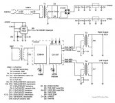
I am using the following schematic now.
Attachments
Hi Quantran,
I am planning to try using the same transformers as yours on an AK4490, could you post a schematic of the way you have yours hooked up ?
Thanks,
PJN
I only connected the transformer primary pins directly from +/- pins , nothing else. I added snubber across secondary pins and plan to add one more filter caps across.
Note that snubber is required (value depends on particular transformer) to reduce ringing as I was testing varous transformers with square wave and scope and see some ringing.
@ Ola:
Funny.,.. I live about 2km from the Dynaudio Headquarter.
I am surpriced that they launched a speaker that will roll off at 8kHz.
I do not see what this has to do with the AK4396 output stage....
But anyway... try the discrete non feedback design, and you will be surpriced....
In our developement model, we had an arrangement, where we could switch in/out both the discrete design and an op-amp based analog stage in the same DAC-PCB. We have tried MANY op-amps, and yes. They all sound different.... But... Still so much alike. The simply sound like an op-amp! None og them was even near the performance of the discrete design.
But among the op-amps, the NE5534A was a true winner!
Wich discrete design did you use ?
Sharpi31: Do you have the pinout for the LL/106SA transformer?Yesterday I replaced the LL1527s in my AK4393 dac and installed BBC spec LL/106SA:
# BBC Type LL/106SA, widely used in broadcast installations
# 1:1 ratio, both windings centre tapped
# Primary inductance 7.8H, dc resistance 49 ohms
# Will handle +12dBm @ 35 Hz, +16 dBm @ 50 Hz, with 600 ohm source & load
# Substantial mumetal can
# Solder terminals
# Dimensions: 44mm diameter x 50mm high, plus terminals and fixings
# Fixings 2 x 6BA bolts, spaced 32mm
Kept the same 8.6ohm series R on each primary connection from dac, but changed secondary load to 15Kohm (amp input impedance 100Kohm).
Way more dynamics and warmth than the Lundahls (I'm sure bigger Lundahls would have better the LL1527s).
Many Thanks,
Owen
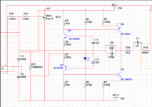
Old thread but, I have been using this with regulated power supply with AK4396(not too bad distortion). *BTW* you can use this circuit without any filter and coupling caps form the dac + channel, the - is left disconnected.
AND BTW, this can be used with TDA1541 with great success by skipping R10, connect direct to R11, important: set the trimmer to nul out the DC offset at the end of the TDA1541, best with OSx4.
If anyone want to improve this circuit or use it as is. I use BC546C in matched pairs instead of the BC546B.
Attachments
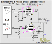
The best solution would be tubes.
Thinking of 12au7 input differential amplifier and Broskie unbalancer with 6DJ8.
Along the lines of a 230 - 245 V power supply depending on the chokes and current around 40ma for stereo.
Still to determinate... dual chokes power supply or single choke.
Input resistor, 330 to 510 ohm Not sure why or not.
10K to ground after dac V out
From page 2 of the schematic:
R1 R2, uncertain 10K to 1M ?
R3 R4, uncertain 300 to 500?
R6, 7R
R7, R8, 24K
R9,R10,R11, R12, 20 to 27K , uncertain
R13, R14, 150 to 250, uncertain,
R15 1M
C5 and C6 filters around 50pf to 60pf
One big question is why not bypass the Rk of the unbalancer?
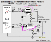
From page 2 of the (internet available, I/V unbalancer) schematic:
R1 R2, Set to 3.3k I was going to use 10K but I found other builders and other schematic with a 2.5K to ground. 3.3K is the ideal resistor that I found by trial and error to load only one side of the signal into a transistor I/V (symmetrical cascode?) and unless the distortion is too high I will keep this resistor, maybe 6.6K would be appropriate too.
Note10 on the manual of AK4396 specify 1.5K minimum for DC load. at 3.3K should keep the dac happy!
R3 R4, Set to 300R
R6, = 7R or a little higher
R7, R8, = 24K (2watts at least)
R9,R10,R11, R12, Set to 20K or a little higher
R13, R14, set to 200 or a little more
R15 = 1M
C5 and C6 filters around 50pf to 60pf
C3 output cap, = 3uf to 5uf with bypass
I wonder if the 300 ohm output impedance would drive HD650 headphones...
Attachments
I am soldering this tonight, in part. Anyone knows anything please help!
I was not sure about the coupling capacitors and the 10K to ground resistors.
the 20K and 20750 resistors can be always adjusted later with a trimpot to minimize 2n harmonics.
All I want is that dac to play clear as possible.
I was not sure about the coupling capacitors and the 10K to ground resistors.
the 20K and 20750 resistors can be always adjusted later with a trimpot to minimize 2n harmonics.
All I want is that dac to play clear as possible.
The best way is first to use JFET buffer to accept signal from dac with high impedance resistor and very low dynamic capacitance of the JFET. Coupling cap should be very low as 100nF to 220nF for 1MEG input JFET section. After that stage HF filter may be employed optionaly to cut out the HF garbage. Again folowed by JFET buffer, low output impedance driver. That will provide range of quality coupling C, and give low JFET buffer output source impedance to drive the interstage transformer.
That lower source impedance lead to have more choice with transformers. The transfrmers in that case does not need to be from very high inductance of the primary, authomaticly less capacitive...
Next because of +6db gain when going from balanced to SE output, it is preferably that transformer have 2x prim : 2 x SEC. For SE output use prallel secondaries.
And than we have full DAC isolation. As option output TUBE buffer can be added after the secondary.
...
There is a little issue or problem with voltage output dac chips, because there is no need to amplify the signal... And only with tube amplification we can add a bit sweeter and less digital less fatiogue sound.
...
Depending of the space of the whole device, tubes can be used for buffer stages
ECC88 for instance have around 200ohms but in prallel sections and 2 tubes per buffer it halves to 100ohms cca. And there interstage transformers wich can be driven for very low F with that driver...
Hi Zoran, did you built an output buffer for the dac ak4396?
I posted this schematic, in all honesty, because it 'bests' unconditionally anything I have heard in opamps.
I have a schematic with BCs transistors, not jfet.... I might share if you would like to show you what you have in mind for the dac. I am not an electronic engineer and this is time consuming for me to design something from scratch from your instructions.
I will not use a transformer in the signal path... no time no money for that.
I will measure my dac, which I only listen by ear so far, the sound was good enough, I trust my ears for that, but I will take some THD and bandwidth readings for your intention.
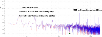
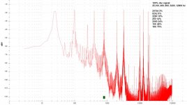
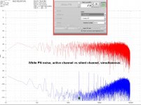
I tested with 13 different tones from the online webpages generator, opened 13 pages lol. and it looks like the resolution is high in the high frequency and around 50 db in the low-midrange. This is not bad at all!
I did then more serious tests, the output is at max around 800mV.
at 750mV : bandwidth (-3db) 7.8 to 68500 hz , THD 1khz 0.010% (+Noise non-A, dBv, 0.023%) at 100hz 0.021% and 0.020%, THD diminish to non-measurable over 5000khz +
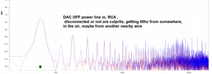
Note that the dac even disconnected has some 60hz interference, it is not in a box
60 hz is air-borne antenna effect of the RCA wires. Even with disconnected power cord it has it as soon as I plug in the measurement tool.
The spikes is from the 'dirty' house electricity, I guess my neighbors CFL, and all the ClassD wall adapters, and fridge motor... They disappear if I disconnect power cord to dac. They go into the rectifier and are amplified in the tube output stage, I guess a power line conditioner would help a lot in a permanent build.
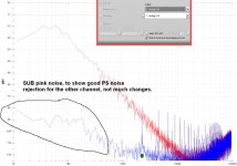
O. more important not to forget, Both channels are the same!, same thd, same response, etc, pretty cool, and almost no cross talk, due to one 10H chokes and 220uf in each tube. hurray, nice work!
I did then more serious tests, the output is at max around 800mV.
at 750mV : bandwidth (-3db) 7.8 to 68500 hz , THD 1khz 0.010% (+Noise non-A, dBv, 0.023%) at 100hz 0.021% and 0.020%, THD diminish to non-measurable over 5000khz +
Note that the dac even disconnected has some 60hz interference, it is not in a box
60 hz is air-borne antenna effect of the RCA wires. Even with disconnected power cord it has it as soon as I plug in the measurement tool.
The spikes is from the 'dirty' house electricity, I guess my neighbors CFL, and all the ClassD wall adapters, and fridge motor... They disappear if I disconnect power cord to dac. They go into the rectifier and are amplified in the tube output stage, I guess a power line conditioner would help a lot in a permanent build.
O. more important not to forget, Both channels are the same!, same thd, same response, etc, pretty cool, and almost no cross talk, due to one 10H chokes and 220uf in each tube. hurray, nice work!
Attachments
- Status
- This old topic is closed. If you want to reopen this topic, contact a moderator using the "Report Post" button.
- Home
- Source & Line
- Digital Line Level
- AK4396: best solution for output stage