And if you don´t like opams,is tfafos the way too go then?
Yes... like in audio note.
Moving Coil etc... - Hifi Collective
You can use this instead of the resistor/capacitor
cap is parallell, resistor i/v, transformer, then another resistor + cap .
---) this goes to tube cathode follower or anode then cathode for more gain.
you can buy the number 450, 496 or 497 from the link.
Please, no opamp!
also check less expensive: SOWTER DAC I/V TRANSFORMERS
Less expensive: From hammond the 140NEx and 140Pex
Less expensive: From hammond the 140NEx and 140Pex
Sorry that I'm so late to this game. I bought a pair of O-netics DAC output transformers from Budp about a year ago and finally got them installed in my Behringer DEQ2496. I used 560ohm series resistors in each leg of the primary with no secondary loading. The bass seemed very rolled off until I jumpered out the series resistors. Now I measure flat output through the bass range compared to 1kHz.
The dynamics are very good and small inner details are much more resolved. But, it seems like the sound gets harsh as I increase the volume. I'm playing at volumes that I've always used but never with this harshness before. I have a low powered PP tube amp. Do you think I'm getting the amp into clipping or near it's limits with the increased dynamics? I have to decrease the volume quite a bit now before this problem subsides. The only thing I've tried so far is adding a 2.2k resistor across the primary since I've seen it mentioned that sometimes a shunt resistor will even out the impedance at higher frequencies.
Thanks,
John
It's good to control THD at the output of your amp at the different volume settings, or, at least check the signal form. There might be the case that you got a bit more amplitude with the transformers (if they work like 1:2 or so), and therefore may overload input bias at the tubes drivers.
Thanks. I recently corresponded with Budp of O-netcs from whom I bought the output transformers. He gave me some good advice regarding the use of primary side series resistance to control the loading on the DAC. I am making progress. He suggested that in the end the optimal value of resistors for sound quality would be something under half of the recommended resistance. Am doing trials now.
John
John
Hi, I'm currently using Tamradio transformers (same as post 203) direct off DAC chip no loading resistors or caps...
Is this optimum? Some people say use nothing and other posts use loading resistors and caps.
Would someone kindly tell me what I should be using with these Tamradio Output transformers? I think they are 600ohm 1:1.
BTW Dac sounds great as is unloaded. Thanks!!
Is this optimum? Some people say use nothing and other posts use loading resistors and caps.
Would someone kindly tell me what I should be using with these Tamradio Output transformers? I think they are 600ohm 1:1.
BTW Dac sounds great as is unloaded. Thanks!!
Last edited:
I can swore by all gods an devils that using of resistor will decries SQ to half.
I had 15 Ohm as "isolation" (witch people crying) for a along time and never satisfied with clarity of sound. just for curiosity soldered the output caps before the resistors. Haven means something now ...
I had 15 Ohm as "isolation" (witch people crying) for a along time and never satisfied with clarity of sound. just for curiosity soldered the output caps before the resistors. Haven means something now ...
Last edited:
Thanks. I recently corresponded with Budp of O-netcs from whom I bought the output transformers. He gave me some good advice regarding the use of primary side series resistance to control the loading on the DAC. I am making progress. He suggested that in the end the optimal value of resistors for sound quality would be something under half of the recommended resistance. Am doing trials now.
John
Great, Look forwards to your findings
")
The minimum resistance specification for a differential V-out DAC is with respect to AC impedance. It is representative of what load the DAC is able to drive. A decent transformer will impose no significant burden on the DAC; it will merely reflect impedance on the secondary to the primary.
So if the transformer secondary is open circuited, you can assume the effective impedance the DAC sees is infinite. The DC resistance of the transformer windings is completely irrelevant. The DAC does not output DC voltage, only AC. AC impedance of an open circuited transformer is for all intents and purposes infinite.
There is no reason to use series impedances on a properly applied transformer/DAC combination. Gain structure is a separate discussion, and better handled by other means. I use the Jensen JT-11-DMPC on the output of the AK4393, which is spec'd for 1k minimum if I recall. Transformer winding resistance 40 ohms. No problems at all, extremely low distortion. It's all about what you connect to the transformer secondary.
Last edited:
I was about to test the output of AK4393 by making 3 different mods on each channel. First naked with just a cap between DAC and amp, second with a Lundahl transformer and third with a simple SRPP tube output. I had the last solution in DEQ and it was amazing.
I got to taking the signal from the ribbon cable to test the naked mod. Sound clarity is great! I feel my SRPP had a bit more dynamics though I also think that taking the signal almost straight from the DAC changed the quality from 3 to 8 in 10 points scale.
Then I decided to change electrolytic caps C6-C11 between X1 ribbon socket and DACs to ELNA Silmic II. It was a silly decision. I burnt the paths on 2 out of 3 channels. These soldering points seem to be a one off thing, at least on my version of the pcb. What is worse is that I can't see how the paths are connecting AKM dacs with X1 socket. Does anyone know if the caps C6 to C11 can be bypassed if I took the signal directly from pins on AKM chips?
I got to taking the signal from the ribbon cable to test the naked mod. Sound clarity is great! I feel my SRPP had a bit more dynamics though I also think that taking the signal almost straight from the DAC changed the quality from 3 to 8 in 10 points scale.
Then I decided to change electrolytic caps C6-C11 between X1 ribbon socket and DACs to ELNA Silmic II. It was a silly decision. I burnt the paths on 2 out of 3 channels
. These soldering points seem to be a one off thing, at least on my version of the pcb. What is worse is that I can't see how the paths are connecting AKM dacs with X1 socket. Does anyone know if the caps C6 to C11 can be bypassed if I took the signal directly from pins on AKM chips?I was about to test the output of AK4393 by making 3 different mods on each channel. First naked with just a cap between DAC and amp, second with a Lundahl transformer and third with a simple SRPP tube output. I had the last solution in DEQ and it was amazing.
I got to taking the signal from the ribbon cable to test the naked mod. Sound clarity is great! I feel my SRPP had a bit more dynamics though I also think that taking the signal almost straight from the DAC changed the quality from 3 to 8 in 10 points scale.
Then I decided to change electrolytic caps C6-C11 between X1 ribbon socket and DACs to ELNA Silmic II. It was a silly decision. I burnt the paths on 2 out of 3 channels
I should have mentioned it was AK4393 implementation in DCX2496
This seems to be an old threat but I am working on the cs4396 with transformer output. I intend to make a LPF filter in front of the primary of the transformer. This is formed by two 330 ohm in series with the primary and two 10nF caps to ground. The cutoff frequency is about 48khz.
Anyone has comment whether this idea is ok in theory?
the transformers I am using are a pair of Edcor wsm600/600. I don't connect the center tap to ground via a resistor. The secondary is floating.
At the moment the sound is extremely detail and dynamic with deep bass but a bit bright. That's why I am thinking some filtering would help.
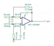
You may do the same with two resistors in phase lines (one per line), and single (!) capacitor connected to the primaries of the transformer.
Good to measure it at the output and tune the values in order to make sure it is flat at highs near 20 khz, as transformers are different, you know.
Good to measure it at the output and tune the values in order to make sure it is flat at highs near 20 khz, as transformers are different, you know.
Tried the filter but the resistor connected to the primary rolls off the bass significantly. 14k termination resistor in the secondary makes the sound having a bit more body.
I guess the termination resistor in combination with the preamp impedance present a more suitable load. Increasing current draw from the ak4396 seems to make the sound more stable.
I guess the termination resistor in combination with the preamp impedance present a more suitable load. Increasing current draw from the ak4396 seems to make the sound more stable.
Last edited:
Tried the filter but the resistor connected to the primary rolls off the bass significantly. 14k termination resistor in the secondary makes the sound having a bit more body.
I guess the termination resistor in combination with the preamp impedance present a more suitable load. Increasing current draw from the ak4396 seems to make the sound more stable.
The signal passing thru the transformer is already doing some filtering. I use another akm dac 4495 and just put a RC snubber across secondary. But I will put in another cap across to do a bit more filtering.
Try out this guru's recommended 1.3db down on 20khz.
http://www.diyaudio.com/forums/lounge/249418-dac-filtering-rasmussen-effect-12.html#post4221347
- Status
- This old topic is closed. If you want to reopen this topic, contact a moderator using the "Report Post" button.
- Home
- Source & Line
- Digital Line Level
- AK4396: best solution for output stage