Bill, Thanks for taking the time.
Yes, I agree about impedance mis-match as a way to transfer voltage (not power, hence the technique of an impedance bridge).
We are at odds over your statement about the transformer not eliminating the DC. This, of course, is common use of a transformer for balanced to unbalanced conversion and getting rid of the DC that the + leg and the - leg are riding on. With two legs going to the two primaries on the Jensen, the voltage at the secondries will still be inverted, but the DC will have been cancelled. I am sure you know this, so maybe something was lost when you glanced at my words.
The term "virtual ground" may have been at bit informal, but it is the way that I had learned things.
Agreed about the inductance, although the cutoff freqeuncy not only depends on the inductance but also the source load (output Z). I did not know if you were disagreeing with that. Whitlock goes over some examples in his white paper if others want to have a look. Perhaps this is why the OP is getting a low freq roll off. I am only guessing at this point.
I am still confused about the resistance that the DAC "needs to see". The spec sheets clearly show that this is a series resistance; however, folks keep referring to a load resistance (which to me implies a resistance to ground).
I think there are just the two of us in this conversation.
If you mean the trafo is isolating the secondary from the DC on the primary, I would agree with that, naturally. If you mean that the trafo is somehow cancelling the DC,then no, that is not correct. You could cap couple one dac output to its series resistor and let the DC feed to the trafo from the other output and it would still work fine. It works differentially, it doesn't care about a voltage potential, as long as there is no DC current flow.
Where does it say the dac needs to see any load. I don't read that at all.
Sorry if I offended you, didn't mean to. I just get very blunt sometimes, a personality fault I've lived with all of my life.
Output trafos are made quite differently from input trafos.
OK, no worries. I don't know anything about the Digitecs, and understood that johnm had no specs for them. Hence the suggestion that they might be incorrectly loaded. If they are output transformers then sure, they aren't bothered about termination. Just scratching around for ideas to fix the problem.
Yesterday I replaced the LL1527s in my AK4393 dac and installed BBC spec LL/106SA:
# BBC Type LL/106SA, widely used in broadcast installations
# 1:1 ratio, both windings centre tapped
# Primary inductance 7.8H, dc resistance 49 ohms
# Will handle +12dBm @ 35 Hz, +16 dBm @ 50 Hz, with 600 ohm source & load
# Substantial mumetal can
# Solder terminals
# Dimensions: 44mm diameter x 50mm high, plus terminals and fixings
# Fixings 2 x 6BA bolts, spaced 32mm
Kept the same 8.6ohm series R on each primary connection from dac, but changed secondary load to 15Kohm (amp input impedance 100Kohm).
Way more dynamics and warmth than the Lundahls (I'm sure bigger Lundahls would have better the LL1527s).
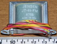
Jensen JT-11 FMCF
I had some Sowter multi tapped transformers on my AK4395 chips in the past and found that I liked the Dayton foil caps better but have been convinced to try transformers again so I bought some Jensen JT-11-FMCF. I will use these direct out with the DEQ2496 running the 4395 and I also ordered a big dac board with DIR9001/CS43122 to join in the chip comparing fun. Jensen doesn't seem to have a spec sheet for the 80% nickel FMCF but the distortion should be closer to the larger 80% EMCF than the FLCF which is the same size but wound on a 50% core to get the price down to $35.
.
http://www.jensen-transformers.com/datashts/11emcf.pdf
.
http://www.jensen-transformers.com/datashts/11flcf.pdf
Attachments
I think there are just the two of us in this conversation.
If you mean the trafo is isolating the secondary from the DC on the primary, I would agree with that, naturally. If you mean that the trafo is somehow cancelling the DC,then no, that is not correct. You could cap couple one dac output to its series resistor and let the DC feed to the trafo from the other output and it would still work fine. It works differentially, it doesn't care about a voltage potential, as long as there is no DC current flow.
Where does it say the dac needs to see any load. I don't read that at all.
Bill, aren't both DAC outputs at the same DC? So when you connect them to the primary, there is no DC current through it because the ends are at equal voltage (DC wise)?
jd
Transformer Basics
Regarding transformers, there are essentially four impedance seen by the amplifier driving the the primary winding.
1. The impedance attached to the secondary multiplied by the square of the turns ratio. For example, if you have a 2:1 trafo attached to a 10k ohm load the primary will present 10k x 2 x 2 = 40k ohms to the amplifier.
2. The reactive impedance of the primary inductance which appears in parallel with the impedance reflected from the secondary. This inductive reactance varies with frequency, becoming a short circuit at D.C. It is also effectively in series with the output impedance of the amplifier, forming a high-pass filter. The higher your primary inductance the lower the corner frequency. The primary inductance can present a very low impedance to the driving amplifier at low frequencies, making it's job much harder rather than easier.
3. The primary winding resistance. Which appears in series with the paralleled pair of impedances from 1. and 2. above. Since the primary inductance will short circuit whatever impedance is reflected from secondary, only the primary winding resistance will be seen at D.C.These three are the relevant impedances at lower frequencies and usually are all you need to be worried about. At higher frequencies the primary's inductive reactance makes it essentially an open circuit leaving the reflected secondary impedance to dominate.
4. There is a small capacitance between the primary and the secondary (two conductors separated by an insulator). It usually is only relevant at high frequencies, but can be responsible for coupling common-mode signals through the trafo which otherwise excel at rejecting common-mode signals (signals which are in-phase at the primary, typically noise) at lower frequencies. A Faraday shield (grounded piece of foil) can be inserted between the two windings used to cancel this coupling effect, and is often found on good input transformers for that reason.
Thanks Bill.
So, in terms of the load the dac sees, the impedance will be that reflected by the load on the secondaries until below the LF limit of the transformer. Below the LF limit the impedance will drop from the reflected secondary load to the primary DCR resitance at 0Hz. Is this correct?
If this is right, there shouldn't be a problem with low series R on the primaries as long as there isn't much happening below the LF limit of the transformer (<20Hz with a decent audio transformer).
Pure speculation on my part - could easily be very wrong (please correct me if so). Just trying to learn")
Regarding transformers, there are essentially four impedance seen by the amplifier driving the the primary winding.
1. The impedance attached to the secondary multiplied by the square of the turns ratio. For example, if you have a 2:1 trafo attached to a 10k ohm load the primary will present 10k x 2 x 2 = 40k ohms to the amplifier.
2. The reactive impedance of the primary inductance which appears in parallel with the impedance reflected from the secondary. This inductive reactance varies with frequency, becoming a short circuit at D.C. It is also effectively in series with the output impedance of the amplifier, forming a high-pass filter. The higher your primary inductance the lower the corner frequency. The primary inductance can present a very low impedance to the driving amplifier at low frequencies, making it's job much harder rather than easier.
3. The primary winding resistance. Which appears in series with the paralleled pair of impedances from 1. and 2. above. Since the primary inductance will short circuit whatever impedance is reflected from secondary, only the primary winding resistance will be seen at D.C.These three are the relevant impedances at lower frequencies and usually are all you need to be worried about. At higher frequencies the primary's inductive reactance makes it essentially an open circuit leaving the reflected secondary impedance to dominate.
4. There is a small capacitance between the primary and the secondary (two conductors separated by an insulator). It usually is only relevant at high frequencies, but can be responsible for coupling common-mode signals through the trafo which otherwise excel at rejecting common-mode signals (signals which are in-phase at the primary, typically noise) at lower frequencies. A Faraday shield (grounded piece of foil) can be inserted between the two windings used to cancel this coupling effect, and is often found on good input transformers for that reason.
Great technical summation, Ken.
May I add about #4. The capacitance IS very small in input trafos because of the use of shielding between windings. Input trafos have many more turns of wire in their construction than output trafos so the capacitance is very important. Output trafos are generally bifilar wound which means the coils are wound together, creating quite a bit more capacitance per turn, but they use many times less turns in their coils. They are also designed to drive a signal through a cable and use their output capabilities to overcome the capacitance. Theoretically, input trafos can be superior to output trafos but once you tie a cable to their outputs you have deviated so far from their designed use that just 2 ft of cable can have serious effects on performance. Add to that the general requirements of proper loading for input trafo secondaries and you now need a signal generator and a scope to set them up properly.
If you have the test equipment and the patience, try input trafos if you like.
If you want to simplify your task with great results, use fine quality line output trafos such as Sowter, Cinemag, Jensen, etc. They are generally less expensive and yield comparable real world results.
That's my rant, YMMV.
Best, Bill
Caps vs trannies
I got my Jensen JT-11 FMCF transformers installed in my modified DEQ2496. The primaries are wired up balanced to the direct outputs of the AK4395 through 20 ohms of my favorite Yageo metal film resistors per leg. I would have used something smaller but that was the lowest value I had on hand of the metal film resisters. No additional load or filters. The AK4395 V out is already well filtered and doesn't need it. The resistors are connected to the same wires at the input of the caps with the trannies mounted outside of the case with their own output connectors wired up single ended with the orange wire grounded inside at the pin 1 that the caps are using. My cables take signal from pin 2 with pin 3 left open even though both legs are available through the caps if wanted for my balanced/ bridged 3875 amps. I currently use my modified Sure 2X100 amps which are single ended and when running a minimal output coil and big SMPS offer by far the best sound I have ever had home.
These are very good transformers. Loss seems to be about only .5-1db compared to the caps. They sound much better than the Sowter multi-tapped volume control transformers that I had tried a few years ago. The Jensens are very close to a good cap. When using the demanding load of my 4k series/ switched shunt stepped attenuators on the inputs of the amps, the balanced in transformers offer a nice full bodied and plump bass compared to a single leg of the dac output through 3uf stacks of Dayton foil caps. The caps sounding a little tighter and lower in level. With the attenuators gone leaving a 20k termination at the amps and using only -.5db digital volume control for the caps, -6.0db for the transformers to match the levels, The advantage in the bass is reduced to a non issue. Still different but more of a toss up of preference between a full bodied plump sound versus the tighter, quicker bass of the caps. From the midbass up the Dayton foil caps really shine. They present with a blacker background with less overhang. On Tattoo from the Janis Ian live cd, the steel guitar at 1:50 is placed much deeper in a blacker sound stage with the caps. The vocals are nicely fleshed out and lacking of additional sibilance with the transformers but the excellent large drums sound slightly filtered. The caps reveal the striking attack and sense of a vibrating membrane much better. The cap's advantage in micro dynamics is even more noticeable on San Andreas fault live where The transformers tend to sound a bit muffled in comparison with more overhang smearing up the presentation slightly. The power and accuracy of Natalie Merchant's voice and attack of the instruments are more engaging through the caps and the crowd sounds go back much deeper and cleaner. On Babylon Sisters, the faint noodling of the left guitar is easy to hear through the transformers but the backing vocals at 1:14 are more separate and distinct with the caps. You get the idea. I like the caps. For the mids and highs of a DCX, a $2 Dayton foil cap is a no brainer compared to spending a fortune on multiple channels of transformers. When increasing the value of the caps to get enough for the bass channel, the price advantage is less, especially if you need balanced which raises the required caps to $24. For full range in a dac with the AK4395/96 the caps will sound more dynamic and revealing.
Next up will be the CS43122 on a big dac board which may need a filter and the extra 6db so I will try the transformers again on that one.
Trannies better quiet
I discovered something by accident the other night. I was on a listening binge with my new DIR9001/ CS43122 Big Dac Board (way better than CS8420/ AK4395) when everyone else in my house went to bed so I had to install my 4k series/ stepped shunt attenuators onto the amp inputs and turn it way down which lowers the input impedance that the direct out dac chips are working into right down toward a punishing 4k whereas the attenuators present a 20k input at a louder -2db setting and the amp is at 20k with no attenuators and only digital volume control which is where I did most of the previous comparison where I preferred the caps. With the increased load and quieter listening level the Jensen transformers clearly sound better than the caps. Why, when the caps sound better at wide open loads and volume? Is it because the transformers are using both legs of the dac chip and the caps are only using one, thereby cutting the output impedance of the dac in half with the transformers. Do transformers inherently "do" current (or quiet?) better than caps? The current is still way less than 1ma. I have never placed much emphasis on the sonics of my system at ultra quiet listening levels but I do know that the AK4395 sounds better working into my amps at 20k than it does at 150k termination so it does enjoy some loading. I put the amps up to 150k to compare my 4k and 20k attenuators and the lower series output impedance of the 4k attenuators sounded best when wide open at -2db even though there is no cable (maybe 6cm of traces) following the attenuators which plug right onto the amp's RCAs. So it is not just that the easiest load wins but maybe 4k is too much load for one leg of these chips when running direct.
I discovered something by accident the other night. I was on a listening binge with my new DIR9001/ CS43122 Big Dac Board (way better than CS8420/ AK4395) when everyone else in my house went to bed so I had to install my 4k series/ stepped shunt attenuators onto the amp inputs and turn it way down which lowers the input impedance that the direct out dac chips are working into right down toward a punishing 4k whereas the attenuators present a 20k input at a louder -2db setting and the amp is at 20k with no attenuators and only digital volume control which is where I did most of the previous comparison where I preferred the caps. With the increased load and quieter listening level the Jensen transformers clearly sound better than the caps. Why, when the caps sound better at wide open loads and volume? Is it because the transformers are using both legs of the dac chip and the caps are only using one, thereby cutting the output impedance of the dac in half with the transformers. Do transformers inherently "do" current (or quiet?) better than caps? The current is still way less than 1ma. I have never placed much emphasis on the sonics of my system at ultra quiet listening levels but I do know that the AK4395 sounds better working into my amps at 20k than it does at 150k termination so it does enjoy some loading. I put the amps up to 150k to compare my 4k and 20k attenuators and the lower series output impedance of the 4k attenuators sounded best when wide open at -2db even though there is no cable (maybe 6cm of traces) following the attenuators which plug right onto the amp's RCAs. So it is not just that the easiest load wins but maybe 4k is too much load for one leg of these chips when running direct.
Last edited:
Big Dac Board
Try this with DIR9001/ CS4398.
.
http://www.diyaudio.com/forums/digital-line-level/137976-experience-diy-dac.html#post1735158
.
CS4397 is even better if you can get that module for it. Direct out through caps or transformers is still the best sounding output for any of these V out dacs.
Hi - did anyone try the THAT corp line drivers instead of the transformers? Also, what are the popular best sounding D/As right now that feature differential outputs? thanks
Try this with DIR9001/ CS4398.
.
http://www.diyaudio.com/forums/digital-line-level/137976-experience-diy-dac.html#post1735158
.
CS4397 is even better if you can get that module for it. Direct out through caps or transformers is still the best sounding output for any of these V out dacs.
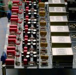
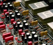
I posted this in Behringer thread but here it is as well since this is great thread as well. 6 channel output with Lundahl transformers and jFets buffers with no caps in the signal path. Signal goes straight from AKM 4396 DACs to transformers. Lundahls are linearized with RC filter - 9Kohm and 680 pF. I came to these values by measurement done on my HP network analyzer which gave me the flatest response. DACs are on Behringer 2496, here is the link for modification I did long time ago:
http://www.diyaudio.com/forums/digi...er-dcx2496-digital-x-over-28.html#post1370646
http://www.diyaudio.com/forums/digi...er-dcx2496-digital-x-over-28.html#post1370646
Attachments
Listening for the best attenuator load for direct out dacs
I listened to my AKM and CS direct out dacs to find the best load for a new stepped attenuator design. I like them into 15k the best. Read about it here.
.
http://www.diyaudio.com/forums/anal...enuator-load-direct-out-akm-cs-dac-chips.html
.
It was also fun to revisit the AK4395 vs AK4396 vs CS43122. The 4395 really does sound way better than the 4396. I had been leaning heavily toward the CS dac chips since getting my Big Dac Board which also allowed me to find the PCM1798 to be not quite as good all of the hype unless you want to implement a no holds barred I/V stage with tubes or discretes instead of opamps. Building a direct out with a V out chip is so much easier for multi channel users and can rival the best sound anywhere with nothing more than a cap to block the dc. I am now liking the AK4395 again when working into the right load. The CS43122 is different but not necessarily better. It has a powerful sound with a little better pinpoint location of the instruments similar to the 4396 but the 4395 throws it's soundstage much deeper behind the front wall and does a really nice job of following the ambient decay and with excellent tuneful bass extension.
Is your volume control RCA in, single ended? If so, to make this test easiest, just cap couple the left and right + output of the dac chip to the center pins, take the original audio ground and then just leave the minus leg floating open for now.
hi Scot,
thanks for your contributions. i run a heavy modded AK4396 kit from eBay with ne5532 as output stage. the signal goes RCA via a stepped 20k shunt attenuator to the 100k-imp SS power amp.
i did this simple test using 2uf 400v Audycap mpk. the 3d was excellent to be on the pair Aureus! but no dynamic and bass!
is there any better "direct out" configuration that you run? with the - output legs as well?
best regards
- Status
- This old topic is closed. If you want to reopen this topic, contact a moderator using the "Report Post" button.
- Home
- Source & Line
- Digital Line Level
- AK4396: best solution for output stage