The most common way is to loop the output of an opa to its inverting input.
Could this be implemented with tubes ?
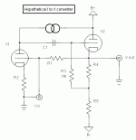
Attached is what grown in my head last night.
My guesses:
First triode is CCS loaded for max gain.
Thus, it's Rk( R2) does not need to by passed.
2nd one is a self biased vy Hi z CF.
R3 being bootstrapped, C1 does not need to be large.
The negative supply allows for the cathode to be set
at ground potential eliminating the need for an
additional link cap at output.
R1 is the earth of the circuit lowering input
impedance to (I guess) zero to acheive I to V behaviour.
How far am I from truth ?
Thanks for any better suggestions.
Yves.
Attachments
The opamp I/V converter you referred to works by inserting the current into a 'virtual earth' terminal. The inv input is at virtual earth because of the feedback (the feedback keeps the inv input at the non-inv input level and that is normally grounded).
So with tubes you should follow the same principle: inject the current into the cathode of the tube and use feedback to keep the cathode at (ac) ground.
Edit: You can do it open loop also. Inject the current into the cathode, put the grid at (ac) ground with the right DC bias for the tube bias current, load the anode with a CCS, pick off the signal from the anode via a cap or go to another level-shifting stage to get down to ground level.
The way your idea is, now the current is injected into a high-impedance node and the i-output of the DAC (which should stay close to ground) is now going to be relatively high voltage level.
Jan Didden
janneman said:The opamp I/V converter you referred to works by inserting the current into a 'virtual earth' terminal. The inv input is at virtual earth because of the feedback (the feedback keeps the inv input at the non-inv input level and that is normally grounded).
So with tubes you should follow the same principle: inject the current into the cathode of the tube and use feedback to keep the cathode at (ac) ground.
Edit: You can do it open loop also. Inject the current into the cathode, put the grid at (ac) ground with the right DC bias for the tube bias current, load the anode with a CCS, pick off the signal from the anode via a cap or go to another level-shifting stage to get down to ground level.
The way your idea is, now the current is injected into a high-impedance node and the i-output of the DAC (which should stay close to ground) is now going to be relatively high voltage level.
Jan Didden
Indeed, inject at cathode. Now, to lower input impedance:
Put cathode signal also differential amplifier with other input grounded, connect output of that diff amp to grid of input triode (and assure feedback takes place rather than feedforward)
best
- Status
- This old topic is closed. If you want to reopen this topic, contact a moderator using the "Report Post" button.
- Home
- Source & Line
- Digital Line Level
- How to build a tubed I to V converter ?


