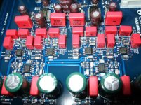
I was just having a peek inside my Cambridge Audio DacMagic.
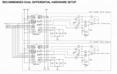
What I find somewhat baffling is that the recommended filter in the WM8740 data sheet (in dual differential mode) uses one op-amp per channel, but Cambridge chose to use SIX per channel (4xN5532 and 2xOP275).
I just don't understand why it's so busy:
What I find somewhat baffling is that the recommended filter in the WM8740 data sheet (in dual differential mode) uses one op-amp per channel, but Cambridge chose to use SIX per channel (4xN5532 and 2xOP275).
I just don't understand why it's so busy:
Attachments
Right, so does that mean I could use a balanced-to-RCA cable and bypass the 2nd dual op-amp? i.e., use only half of the balanced signal? I think there will be a S/N penalty of 3dB but I won't lose sleep over that.
I can't help thinking that the 2nd op-amp (OP275) is what gives the unit its overpowering bass, as this is exactly what the OP275 sounds like whenever I've used it anywhere.
It's difficult to tell, but it looks like maybe one half of one DAC produces the +ve half (summing LP and LN in a diff. amp) and the other half of one DAC produces the -ve half (using RN and RP pins). Why it still then takes a dual to sum them both remains a mystery though.
It uses a pair of WM8740 dacs, which are V-out dacs.
In mono mode, you get two positive and two negative per DAC chip, but it seems they combine one pair of V+ and V- to produce 'V+', and then combine the other pair V- and V+ to produce 'V-'.
These provide the balanced outputs. Then they combine the V+ and V- again to produce the unbalanced (in the OP275).
That's how it seems to me anyway.
I just knocked up a couple of adaptors. Shield to pin 1, signal to pin 2, pin3 left unterminated. I think it sounds better. The stereo image is quite a bit wider wider.
Me again....
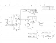
I've been looking at the schematics of the Cambridge 740C CD player, but the circuit is the same bar a few component value changes.
A similar circuit is also used in the 640C, 640CV2, 750C...
What is the purpose, or indeed benefit of this configuration of op-amps?
There's a kind of inverted output signal into the non-inverting input of the first op-amp, so two feedback loops. Kind of like an OPA1632 or THS4131 made with two halves of an NE5532??
Does this configuration have a name? I have not seen it before.
Is the second op-amp considered to be in the signal path, or rather, is this more like a single op-amp application?
How much affect would the qualities of the second op-amp have?
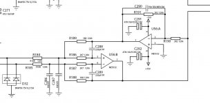
Here's a bit of the schematic, note that it is only half of one channel (one phase) and it then goes through more op-amps to go bal->unbal.
I've been looking at the schematics of the Cambridge 740C CD player, but the circuit is the same bar a few component value changes.
A similar circuit is also used in the 640C, 640CV2, 750C...
What is the purpose, or indeed benefit of this configuration of op-amps?
There's a kind of inverted output signal into the non-inverting input of the first op-amp, so two feedback loops. Kind of like an OPA1632 or THS4131 made with two halves of an NE5532??
Does this configuration have a name? I have not seen it before.
Is the second op-amp considered to be in the signal path, or rather, is this more like a single op-amp application?
How much affect would the qualities of the second op-amp have?
Here's a bit of the schematic, note that it is only half of one channel (one phase) and it then goes through more op-amps to go bal->unbal.
Attachments
Have you tried using just the + half of the balanced output? It's still made from a differential pair of DAC outputs (important for common-mode noise rejection), but avoids half of the output stage (importantly avoids the OP275). Sounds much better. No o/p caps needed either with 1-3mV of DC that's all.
You lose a few dB of s/n as only using one half of each DAC (not a problem) and you still get the channel separation benefits of two DACs.
I would probably rip out the final stage and the -ve half of the first stage and just use a decent op-amp for what's left, DC coupled all the way. Not a fan of the LMs though so that one's out.
Opened up a new thread btw:
http://www.diyaudio.com/forums/digital-source/154442-op-amp-circuit-question-dac-o-p.html
- Status
- This old topic is closed. If you want to reopen this topic, contact a moderator using the "Report Post" button.
- Home
- Source & Line
- Digital Line Level
- DacMagic output stage