Hi aptsys, any suggestions on fixing the feedback loop would be greatly appreciated. AD797 sounds so good that I am decided to go all the way.
On another topic I reworked the clock supply and now have a) Crystek XO relocated to DAC PCB, b) removed the FBs for both XO & Schmitt inverter and powered both from the flea 3.3Vdc, c) replaced XO & Schmitt inverter ceramic bypass caps with film Panasonic ECHU 0.1nf/50V (0805).
With this change the whole clock chain is in clean supply except of the DSP. The AD797 on the flea PSU gets warm but nothing to worry.
This feels to have added further improvement to the sound stage, definition and bass.
Attachments
@gvelim
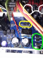
- you can replace regular diodes with schottky diodes (green circle)
- use SP-Cap, glue it on the top of Potato chip and connect to pins 14 in 7 (yellow circle)
- for VMIDL and VMIDR you need low leakage type capacitor and Oscon's are high leakage: http://www.saga-sanyo.co.jp/oscon/cgi-bin/e_sizecode.cgi?id=SEPC. I tried different caps there, including Nichicon KL (lowest leakage). Personally I like Panasonic FC or FM there (white circle). You should try different caps and values in this position and decide for yourself
For AD797, try to lower power supply lines to 12V to minimize power dissipation.
Attachments
Last edited:
Thanks Stormsonic for the good advise, will try out the rest but AD797 since I am bit stuck on +/- 15Vdc as otherwise I have to change the SuperRegs so not sure whether I have any option here.
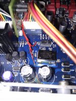
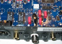
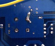
My last mod (flea PSU -> XO+HexInv) although it improved on bass and stage detail I noticed that caused the highs to be distorted, particularly the sound of the hi-hat was sounding muddy.
I reworked the mode to add the ferry beads which fixed the problem and made the sound pristine again, "hi hat" sounds as a "hi hat", etc. Seems some HF return spoiling something there, not sure though what happened.
I attached photos of the final change as I hope that I am done with the clock (can't get any better, or is it ?)
Attachments
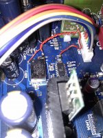
Great, you isolated chip and crystal with ferrite beads. Maybe bigger capacitor after ferrite beads (SP-Cap parallel to C32 and C121).
You can also rework digital input buffer for Coax Digital input 1 and Coax Digital input 2, but you will need 0805 SMD resistors:
R20, R22 = 4.7K
R21, R23 = 68K
R65, R86 = 2.2K
R87, R125 = 10K
While there, please remove capacitors C17 and C18, they are doing a lot of harm in this position.
If you want to improve things further, C126 and C127 should be replaced with piece of wire.
You can also move output film capacitors to new position, solder them across C12, C14, C215, C222. Recycling
Attachments
Last edited:
Nice one Stormsonic
Considering the re-clocking and up-sampling that takes place in the DSP would any improvements in the input make any difference ?
Isn't the purpose of the DSP/memory buffer to cancel all those bad effects of the input ?
You can also rework digital input buffer for Coax Digital input 1 and Coax Digital input 2
Considering the re-clocking and up-sampling that takes place in the DSP would any improvements in the input make any difference ?
Isn't the purpose of the DSP/memory buffer to cancel all those bad effects of the input ?
Hi aptsys, any suggestions on fixing the feedback loop would be greatly appreciated. AD797 sounds so good that I am decided to go all the way.
Hi,
Is the AD797 in place of all the op amps at U55, U56, U59 and U60, or are the ones for differential to single ended also replaced?
Do all of the AD797's run hot or is it only certain ones?
Stormsonic, can you please make a summary of which mods you recommend for the best possible sound? You seem to be the one to ask!
I have made the basic mods with super regs for 5+ and 15-volt, and bypassed the output caps, now I want more!
The relays at the output, are they affecting sound quality in a negative way? Can they be removed in some way?
I only use toslink-input and xlr-output. Will I gain anything from disabling usb,coax and the rca-outputs?
Last edited:
@Rajapruk
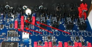
About relays : I have bypassed relays 3 ,4 , 5 ( mind not relays 6 ) last week with no noise on switch on/off, nor when switching sources too ( tanks to WOLFSON'S guys for well implemented digital mute ) . Don't know if is a big change because, in same time, I made a couple of more mods....
ciao.
Nice
I have made the basic mods with super regs for 5+ and 15-volt, and bypassed the output caps, now I want more!
I highly recommend your next target is to fix the master clock before any other improvements as otherwise you won't have a good foundation to assess a mod's effect - my personal experience.
Replace XO and HEX Inverter, power them from a Flea PSU with the appropriate cap selection for bypassing. Highly recommending Crystek XO (CCHD-957) and PotatoSemi Hex Inverter (PO74G14A).
stormsonic said:Great, you isolated chip and crystal with ferrite beads. Maybe bigger capacitor after ferrite beads (SP-Cap parallel to C32 and C121).
@ Stormsonic, complemented the XO PSU bypassing with a 0603/NPO 470pf and 1206/ECPU 0.15uf in addition to the 0805/ECHU 100pf and which fit very nicely in the +Vss pad and the 2 surrounding little GND holes. The compo of 0603/0805/1206 is highly recommended due to the ESL differences of the packaging.
I confirm this has positive impact to bass and stage clarity.
Changed the Diodes to Schottky however I haven't noticed any improvement with this mod.
Attachments
Last edited:
Hi all,
I've got the UWB module for the replacement of the 7805, 7815 and 7915.
The 5V one working fine. But the 7815 and 7915 one working hot like burnning.
I replace the NE5532 to the LM49720. Is it the reason to draw much current from the modules?
I've got the input voltage of the modules is around +-23V.....
The power transformer modified with the R-core AC12V in 30VA.
Thanks!
From experience it gets hot to the point you cannot touch the heat sink for more than 5". Your option is to replace the 56R resistors with 100R to decrease power dissipation ... ensure the voltage drop doesn't affect the min Vin tha UWB requires.
If you don't use RCA you can remove the opams too so you can reduce current draw.
Also you can feed the 7505 UWB from the UREG to further relief the 7515 UWB
Finally you could go for 9V transformer as long as your UWB can handle the voltage drop. Bear in mind this approach streches the DC/DC buck converter in the digital psu.
For me the 100R/4W worked well, but made sound a bit brighter.
Now I need to remove the 15v modules until I found the solution of it.
Have you excluded one or more OpAmps oscillating ? How much is the voltage drop against R400 ?
matcc said:I would like to know is the MC34063 just for step down to 5V in higher current? Can I just pass it with the 7805 something
If you do this, you will have 7805 to deal with 16.8V at its input which will be a lot of power to dissipate. The MC34063 does this very efficiently especially more comfortably the higher the input voltage is. Hence MC34063 was purposefully put there.
Hi,
Is the AD797 in place of all the op amps at U55, U56, U59 and U60, or are the ones for differential to single ended also replaced?
Do all of the AD797's run hot or is it only certain ones?
Hi aptsys, here is the setup with the AD797
http://www.diyaudio.com/forums/digital-line-level/142184-opening-new-dacmagic-41.html#post2890834
All 4 of them feel equally hot on the browndogs.
Assuming in this setup, 15mA go to the SRegs + 2 x OPA2120 and with
1) R400 at 100ohm I measured 5.86 voltage drop which gives 11mA per opamp
2) R400 at 56 ohm I measure 3.84 volatge drop which gives 13mA per opamp
hope that clarifies the situation
Last edited:
Have you excluded one or more OpAmps oscillating ? How much is the voltage drop against R400 ?
It is 5.22V there......
5.22V across R400 translates into 93mA spared across Dexa UWB and the 6 x LM49720 which you can assume for each consuming 10-14mA. That is 0.45W @ 30V Rail-to-Rail per opamp and with thermal resistance @145C/W you should be looking at around 80C at room temperature.
LM49720 datasheet gives idle current of 10mA which drives 0.3W @ 30V RtR, which again is > 60C temperature.
Unless you have a high bandwidth oscilloscope to check the outputs for oscillations then you cannot tell whether the high temp is normal or due to a flaw in your mod.
I had cases of oscillations because of opamp bad soldering that got fixed after re-soldering the IC.
Thanks for the help!
Now I just put the 78/7915 back there. Becoz I found the sound after the modules mod not as well as the original one. Ok, the transparency is better and the soundstage bigger. Great performance but not musical.
I've ordered the OP1642 for the last stage for the RCA output already. I tried to bypass and get the output from Phase + of the Balance. Also great performance but not musical to my system. That's why I keep it.
I am thinking to separate the digital and analog power. The plan is 78/7915 get the power from the other 12-15VAC transformer. I think this would be the easier way to reduce the heat problem and make the sound better, right?
- Home
- Source & Line
- Digital Line Level
- Opening the new DacMagic????