Good Good Friday Morning to you all,
I'm designing a 3rd Order Bessel Filter for my 8xOS DAC, and its great fun!
I'm using several books, but mainly Lancaster's Active Filter Cookbook (because I have forgotten how to add), and LTSpice to simulate.
Unfortunately, I'm not sure how to get the FFT mode on to give me a sensible frequency domain transfer function - probably my input needs to be white noise or something - any ideas? Probably different software, but manually changing the input frequency and measuring the output seems to be reasonable enough.
Anyway, as I said, I'm trying a 3rd Order Bessel for best group delay. However, its not optimally flat (unlike a Butterworth) so I'm trying to make use of the luxury of 8xOS making the job of analogue filtering easier and using quite a high cut off frequency - so that the filter doesn't really start dipping until it is past the audio band. So I've looked at various cut off frequencies from 50 to 100kHz.
Now, what sort of attenuation do I need by the sampling frequency (352.8Khz)? My 50kHz Bessel attenuates a 3V input down to something like 20mV at 400kHz, but is down nearly 0.7V at 22.1kHz. 80 or 100kHz is better, only dips by about 0.4V at 22.1kHz, but likewise only down to 80mV at 400kHz.
So, my question really is, what kind of attenuation do I need around Fs? I suspect a lot of the energy that far up in the spectrum is not faithfully reproduced, but can still cause IMI if not filtered sufficiently.
BTW, this is a PMD100 digital filter chip. I suspect that's important. For instance an SAA7220 has a sneaky boost at the high end of its audio band to counter this dip in the Bessel filter.
Thinking that increasing the order would make the dip worse, I tried second order, but that actually did what I was trying to avoid. So I will investigate 4th order. I'm probably not interested in steeper cut-off, more into less dipping in the audio band.
Or, am I worrying too much?
It should be easy to knock up a generic filter circuit, and mess about at some point. To see if these limitations have any actual impact in reality.
Cheers,
Phil
Hi,
What DAC are you using? A good reading is the AN of the old AD1862. They came to the conclusion that a 7th order equiripple is needed for an 8xOS.
I think that a 3rd order Bessel with -3dB@50kHz or so is good enough. FDNR is a good topology, if you want you can add more poles relatively easy without penalties on performance.
If you need the AN (~1Mb) send me an e-mail.
Yeah, I thought 50khz Fc would be suitable, and probably is.I was just a little surprised to see it dip so much at 20kHz.
I suspect I will try this and see how I get on with it. With my hearing it probably won't make much difference.
I think I've come across that doc in the past.I shall have another look.
And, its a TDA1541A DAC. I think the digital filter is probably of more interest than the DAC though.
(what with all DACs being equal") )
)
(that was a joke!)
I suspect I will try this and see how I get on with it. With my hearing it probably won't make much difference.
I think I've come across that doc in the past.I shall have another look.
And, its a TDA1541A DAC. I think the digital filter is probably of more interest than the DAC though.
(what with all DACs being equal
)(that was a joke!)
Well the CD player you thought had more treble than yours last time you popped round actually measures 0.85dB down at 20K, cf. theoretical 0.80db. I had to check,but that's close enough for me... esp after the interference it has been subjected to!
PS beers in the fridge if you get bored Happy Easter, fella.
PS beers in the fridge if you get bored
Happy Easter, fella.Well, I've built it.
It has some issues regarding decoupling. In some cases I have electrolytics perhaps a cm or so from some opamps, so I definitely need smaller decoupling caps closer to the opamps. I'll probably solder some directly underneath the socket. So at the moment its really not happy with fast opamps, which would be useful for the IV stage.
However, using some quaint JRC2114s donated by my old CD63, I'm rather pleased with the results.
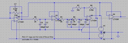
So, it consists of an IV stage, then a passive 1st order filter, an opamp buffer, then a Sallen-Key 2nd order filter (incoporating an opamp) and a final opamp as a buffer.
I previously had issues with the passive stage, combined with the interconnect and preamp input impedance being hard to drive, so I've paid attention to removing that as much as possible, hence all the buffering. The opamps are socketed, so I can bypass one or both voltage followers if needed.
(BTW the RC filters are all 2k vs 1.xnF, but I had to use 2.2k - is that a major flaw? I'll change the resistances one day).
Initial impressions are great! There is much more detail. The sound stage is improved, and even things like percussion and rhythm seem better. I thought I'd do a quick test, a few excerpts from a selection of tracks, yet somehow ended up just listening to stuff in it's entirety. It was really interesting and enjoyable to listen to.
I need to tidy stuff up a bit, and especially improve decoupling, but for a first draft I'm rather impressed.
And I have deliberately left room for a relay for switching the gain for HDCD
It has some issues regarding decoupling. In some cases I have electrolytics perhaps a cm or so from some opamps, so I definitely need smaller decoupling caps closer to the opamps. I'll probably solder some directly underneath the socket. So at the moment its really not happy with fast opamps, which would be useful for the IV stage.
However, using some quaint JRC2114s donated by my old CD63, I'm rather pleased with the results.
So, it consists of an IV stage, then a passive 1st order filter, an opamp buffer, then a Sallen-Key 2nd order filter (incoporating an opamp) and a final opamp as a buffer.
I previously had issues with the passive stage, combined with the interconnect and preamp input impedance being hard to drive, so I've paid attention to removing that as much as possible, hence all the buffering. The opamps are socketed, so I can bypass one or both voltage followers if needed.
(BTW the RC filters are all 2k vs 1.xnF, but I had to use 2.2k - is that a major flaw? I'll change the resistances one day).
Initial impressions are great! There is much more detail. The sound stage is improved, and even things like percussion and rhythm seem better. I thought I'd do a quick test, a few excerpts from a selection of tracks, yet somehow ended up just listening to stuff in it's entirety. It was really interesting and enjoyable to listen to.
I need to tidy stuff up a bit, and especially improve decoupling, but for a first draft I'm rather impressed.
And I have deliberately left room for a relay for switching the gain for HDCD
Hi Martin.
Yes, I must visit and show you the latest installment of my comedy DAC
Well, I've managed to get it to work with faster opamps, but I'm concerned by the solution.
There was a nasty crackling noise in both channels with faster opamps (JRC 2114 was fine, but the LT1361 or LM4562 had this noise).
I added 100nF caps underneath the sockets as further decoupling. That didn't actually help.
Then, by accident, I discovered that if I put 100nF between gnd and just one of the inputs to the opamp IV stage, the problem is solved! So, essentially the same as a cap across AOR and GND, but at the other end of the cable. I didn't need a cap for each channel, just the one.
Any idea what could be going on there? I wonder if the problem is at the DAC end, rather than the IV stage.
Anyway, the noise is fixed. I have LM4562 for IV conversion, 2x OPA2107 for the filter, and a further LM4562 for the output stage. It sounds truly awesome (to me anyway). It is so much better than it was. I had no idea how bad my output was previously (in my defence, I had just knocked it up simply just to get it working).
Well, if that cap works, it works: my bet would be it shortens some kind of 'long-way-round' at HF, ho ho. Need a scope, or a long stare at the reality, to check though. Do let me know when you are free, the calendar is sadly empty this end!
To everyone else reading - with the phraase 'comedy dac' Phil is rather understating his talents
To everyone else reading - with the phraase 'comedy dac' Phil is rather understating his talents
Indeed it works, so, umm, leaving it for now. Not my most professional moment interestingly, one for each channel allows the noise back! Nice.
(I am a professional, honest, but not in DIY DACs).
You're right, it's more comedic these days. I'm actually very pleased with it now, but it does sort of have its own enclosure I built for it - that it has now outgrown. Veroboard modules overflowing the front, like some kind of surreal flood. It does ooze with audiophile look and feel.
I have a new box for it all to fit in, although, I'm tempted to stack the boards into a cuboid - like that 4xTDA1541A thread elsewhere. But, before that, I still have to get my relay switching going for HDCD gain.
interestingly, one for each channel allows the noise back! Nice. (I am a professional, honest, but not in DIY DACs).
You're right, it's more comedic these days. I'm actually very pleased with it now, but it does sort of have its own enclosure I built for it - that it has now outgrown. Veroboard modules overflowing the front, like some kind of surreal flood. It does ooze with audiophile look and feel.
I have a new box for it all to fit in, although, I'm tempted to stack the boards into a cuboid - like that 4xTDA1541A thread elsewhere. But, before that, I still have to get my relay switching going for HDCD gain.
No, you need AN-207:
http://www.analog.com/static/imported-files/application_notes/383160163AN207.pdf
http://www.analog.com/static/imported-files/application_notes/383160163AN207.pdf
philpoole said:Sorry, four opamps instead of one - that DAC has a voltage output.
All I wanted to say is that a third order Bessel filter is more than sufficient if you are using an 8x oversampling digital filter.
I think even one passive low pass filter will do.
I am looking forward to your schematic.
I did have a passive filter, and my opamp was struggling to drive it. It worked okay, but this is much better.
Anyway, here's the schematic. There's no attention to bypass caps, and grounding, and I'm not using LT1361s, and the multiple caps in parallel is just because I was using bits I had to hand.
Anyway, here's the schematic. There's no attention to bypass caps, and grounding, and I'm not using LT1361s, and the multiple caps in parallel is just because I was using bits I had to hand.
Attachments
- Status
- This old topic is closed. If you want to reopen this topic, contact a moderator using the "Report Post" button.
- Home
- Source & Line
- Digital Line Level
- What would be a sensible set of filter characteristics for DAC