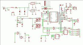
I made a circuit with PCM2707 using an extarnal regulator to generate +3,3V. It works but I measure +4V on the regulator output. I changed the regulator but the +4V always is there. So I think that it's due to the PCM2707: in any way the internal regulator is working olso if I disabled it.
I post my schematic.
Any help will be appreciate
Thank you
Aiace
I post my schematic.
Any help will be appreciate
Thank you
Aiace
Attachments
Your image's resolution isn't very good, so I can't see what's going on, but when I find a Low Dropout Regulator that isn't regulating, I always look to see if the output filter capacitance is suitable. Some parts are happy with ceramics on the outputs, some need the ESR of an electrolytic for stability, but nearly all of them require some sort of capacitor on their output to maintain stability. The LT1963, for example, requires a 10 µF capacitor. Again, I can't really see your schematic very clearly, but I don't see such an output capacitance.
Did you measure the 4V with a DMM or observe the output waveform with an oscilloscope?
Did you measure the 4V with a DMM or observe the output waveform with an oscilloscope?
thank yoo RCO3.
I measured it with the oscilloscope.
I am not able to attach a bigger picture here, so a try to write.
The LT1963 has 1uF ceramic cap soldered between output-gnd pins followed by one 150uF Os-con electrolitic.
What I see with the oscilloscope is that the Vbus pin of the PCM2707 is 4V and very noisy so I had soldered 1uF between Vbus pin anf gnd ( if I soldered it few mils away it was worthless). Without this 1uF cap the sound sucks.
I 'm becoming to think that the PCM2707 is dameged, maybe the internal regulator is working even if I desabled it.
Infact I'm using another LT1963 for the analog part of PCM2707 and it works very well.
Any clue?
Thank Aiace
- Status
- This old topic is closed. If you want to reopen this topic, contact a moderator using the "Report Post" button.
