Hi,
My first post here. I've been mildly audiophile for many years, and have done minor electronic tweaking (output stages, caps, power supplies) in the past but remain pretty clueless about the digital world.
My system (a few years old...)
-Micromega stage 2 cd player
-Audiolab 8000P+C amps
-PSB stratus silver speakers
The Micromega is either leaving or getting updated. Mine has always worked flawlessly, so I must have been among the lucky few.
Possible updates are:
-Tentlabs or D-clock (www.newclassd.com) clock, with dedicated power supply
-separate power supply for analogue section (transformer, caps and regulators, like the Tentlabs shunt regulator)
-new opamps (NE5534N originally)
Any feedback/suggestions on these? Will it improve the sound, or should I go for an other player? Rather like the sound though...
One possible show stopper: Several references online suggest the stage 2 is equipped with saa7321 converter, which appears to be of rather nice quality. I opened mine, however, and underneath the mother board i found 2x TDA1305T, as I understand a budget DAC found in Cambridge DACMagic and others.
Question remains then, how much further can I go, sonically, with this converter?
Any feedback/hints/suggestions are most appreciated!
Cheers!
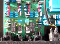
I'm not so sure that the TDA1305 is a "budget DAC". I have a Micromega DAC1 which IMHO sounds great (as good as my Primare D20 with 24 bit/96 kHz DAC). The analogue section may be a bit more state-of-the art than in the Stage 2, though. You won't find 5532/5534 in a DAC1 and the single ended (RCA) outputs are DC-coupled; it also has balanced outputs (XLR). And yes, the DAC1 also has the TDA1305.
My suggestion would be to start with the analogue section (the attachment is the analogue section of the DAC1).
My suggestion would be to start with the analogue section (the attachment is the analogue section of the DAC1).
Attachments
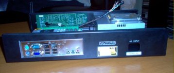
I have a Stage 2... wouldn't swap at the moment for anything. Owned from new and modded as follows. The "first" Op amp from the DAC is the I/V convertor, I replaced this with OPA604AP and the buffer with AD845JN. The output from pin 6 to the muting relay, cut the print and added a 68 ohm series resistor to isolate the output of the Opamp from any cable capacitance. Add a 0.1mfd across the supply pins of the OpAmps soldered on the pins, not supply to ground. I also replaced ALL the electroylitics in the whole unit, adding 0.1mfd surface mount caps across most of these on the print side. They fit perfectly, looks factory original. I also added a TOSLINK output ( fitted to the removable aluminium plate ) on the rear for connection to a Mini Disc recorder.
It's an amazing player even after all these years. I was lucky, got hold of a new Japanese CDM12.4 mech which I fitted recently.
It's an amazing player even after all these years. I was lucky, got hold of a new Japanese CDM12.4 mech which I fitted recently.
One other thing, the multiturn pot sets the output at zero volts dc, and this limits your choice of OpAmp unless you mod that part of the circuit. The AD845 will work as is and sounds great. Worth doing IMO. Also the board is not easy to work on as all the holes are plated through vias so you will have to cut each leg of the IC to remove, then use braid or a sucker.
Thanks for replies and tips!
Feedback like this is exactly what I need, the feeling I had about keeping the stage 2 is definitely reinforced. But it will not go unaltered (the player, that is...) !
I'll definitely look into the analogue stage. AD845 could be an option, and I have seen others recommending OPA627 or AD797. Hard to know which is best, I've never listened to any of them, haven't checked availability either.
jitter: Thanks for the DAC 1 picture, I tried to see what kind of opamps that were close to the multiturn pot in your picture, as I guess that would be the buffer, but I'm not able to read the text on it. It could look like LT1227, is that right?
I'll still check out the clock upgrade though, no fortune and fun to fiddle with.
The AD797 will require modification to the circuit for the offset null to work correctly. I would definitely try the opamps first before even thinking about any clock mods. The clock is closely integrated into the PCB design and adding a separate unit may make things worse, it's as much to do with layout as anything, sending the clock signal down an inch or two of wire can negate any benefits. I chose the opa604 because it has even harmonics as the predominating distortion, which is the most pleasing to the ear. Beware of using any ultra hi bandwidth opamps, they are just not needed for CD. I also don't like sockets, and please don't underestimate actually removing the devices to begin with. You will have to cut them out and clear each hole separately, the PCB is of extremely high quality but some of the print is very fine... beware. But it's all worth it !
So out went the AD797. I'm not wanting to fiddle with the rest of the output circuit.
Talked to Guido Tent yesterday though, he recommended OPA134 over the AD845. I'm not gonna let this descend into an opamp thread, but does anyone know if the 134 can be used directly in the Stage 2? I might want to install sockets and listen to both.
Mooly: You mean you just added the resistor across the cut in the print?
thanks!
jono799 said:jitter: Thanks for the DAC 1 picture, I tried to see what kind of opamps that were close to the multiturn pot in your picture, as I guess that would be the buffer, but I'm not able to read the text on it. It could look like LT1227, is that right?
LT1227 is correct.
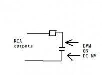
The 134 shoud be fine. If you do use sockets I would definitely add a small ( 0.1 to 0.47 mfd ... not critical ) soldered neatly to the top of the supply pins on the IC itself. Do it well and it won't interfere with the IC going in a socket. The 68 ohm ends up in series with the output, so yes it's just across the cut. To tweak the trimmer correctly, connect a 22k or thereabouts resistor and cap as shown to the outputs... you must use the RCA ground... ideally make this up on an old phono plug... easy... and tweak the trimmer for 0.00vdc... You get a more accurate reading with the filter as any hf noise upsets DVMs or use a scope of course.
If you use sockets try a few different combinations of opamp... and just for fun try 741's... oh and TL071 are surprisingly good, better than the 5534's
If you use sockets try a few different combinations of opamp... and just for fun try 741's... oh and TL071 are surprisingly good, better than the 5534's
Attachments
A tip for clearing the vias of solder. You will have to snip each IC leg with cutters, removing each separately. If you can get hold of some stainless wire to poke thru each hole as you heat it that can help remove the solder. A sucker may work, braid I found didn't very well, the print is too fine... you want it to end up like new afterwards.
All right, now I am playing with 2x opa604's and 2x AD845's!
(haven't modded any caps or resistors yet though. And getting those old ICs out from the print was nerve-wrecking...)
Have only listened for a few minutes, but I can certainly say that the overall sound has improved, and I hear stuff from my CDs that I didn't hear before. Need to listen more in order to give any conclusions, but it sounds very promising!
Now, I also had an idea to install a separate power supply for the DAC/analog board. Anybody have any tips for how to do his, or whether it pays off? There is a rectifier with 30V ac input on the board, my basic idea was to simply cut the print supplying the rectifier and connect it to a separate transformer instead.
Will that work, or will I mess something else up by doing this?
Cheers
Pleased to hear you fitted the IC's OK. Do add that 68 ohm from pin 6 to isolate the device from any cable capacitance effects.
My feeling on the transformer is don't do it. The player is designed as "a whole" with carefull attention to grounding configurations etc. The supplies are all very well regulated, I think it could end up worse IMO
It's worth adding those 0.1 caps across pins 4 and 7 though to give a low impedance at HF on the supply.
Remember that even a 100% theoretically perfect supply is only perfect at "one" point. A few centimeters of copper track, a bit of resistance and inductance, cross coupling between adjacent tracks and it soons picks up noise.
Was the offset OK ?
Micromega stage 2 mods
Hi all,
My system:
Micromega Stage 2
Talk Electronics 2.1
PMC DB1+
I am new to this forum but i am interested in upgrading my Micromega Stage 2. Unfortunately I have not used a soldering iron and to say the least I am a bit reluctant. If i got the neccesary op-amps, mount caps etc, is there anybody that could fit the upgrades for me, I live in Herts and work in London. Obviously suitable recompense will occur. Failing that, would you know of any companies that could take on the work and what are the best upgrades.
Thanking you in advance,
Simon.
Only just seen your post (new members still under moderation don't trigger the thread notifier).
Fitting opamps isn't beyond the realms of a beginner... but you would have to be very carefull and use the right tools to do it on the Micromega.
The Stage 2 is a delight to work on as the main PCB just unclips from the chassis with a couple of push on connectors to ribbon cables. Two minutes of a job to remove completely.
You need a good soldering iron, some solder braid and a thin piece of stainless wire (approx 1mm or so diameter) to help clear the vias of solder. And a good pair of cutters.
The rest is just care and patience")
Fitting opamps isn't beyond the realms of a beginner... but you would have to be very carefull and use the right tools to do it on the Micromega.
The Stage 2 is a delight to work on as the main PCB just unclips from the chassis with a couple of push on connectors to ribbon cables. Two minutes of a job to remove completely.
You need a good soldering iron, some solder braid and a thin piece of stainless wire (approx 1mm or so diameter) to help clear the vias of solder. And a good pair of cutters.
The rest is just care and patience
Thank you for your reply, Mooly, appreciate it. Where can i purchase the op amps and the necessary equipment. Also I am going to need deatailed instructions as i've never held a soldering iron before. Still a bit apprehensive, need to just bite the bullet.
Have you had any dealings with Chevron audio or Trichord could they carry out the work?
All the best,
Simon.
Have you had any dealings with Chevron audio or Trichord could they carry out the work?
All the best,
Simon.
If you fancy having a go, I would suggest practicing soldering on some old piece of scrap equipment... anything... old radios, remotes, that kind of thing. See if you are comfortable doing that. You need a decent iron... not one with too fine a tip either you need plenty of heat to unsolder and use braid.
Something alonf the lines of,
ANTEX|K98J470|KIT, SOLDERING IRON+STAND+SOLDER | Farnell United Kingdom
Farnell also do all the opamps (a lot anyway)
I used,
TEXAS INSTRUMENTS|OPA604AP|OP AMP, VFB FET I/P, 8PDIP | Farnell United Kingdom
and,
ANALOG DEVICES|AD845JNZ|OP AMP, FET FAST SETTLING, DIP | Farnell United Kingdom
If it is something you might have a go at... and the only "hard" part is removing the original I/C's then I'm sure it's something you could be talked through.
The secret is don't rush and to ask if not sure
It might also be advisable for you to fit sockets so you can continue swapping Opamps with no additional soldering.
I have had no dealing with those companies... sorry.
- Home
- Source & Line
- Digital Line Level
- Micromega Stage 2 modification - and incorrect info...