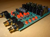
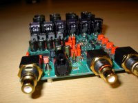
Here´s a few shots of the latest edition of our DAC project.
The Chips chosen are CS 8416 and CS4398.
The supply for the digital section consists of its own transformer (UI core), rectification, smoothing and then 2 LM317 preregulators befollowed by 4 discrete ultrafast regulators, 2 for analog circuitry in the chips and 2 for digital logic.
Filtration is done passively with high quality parallel caps with 2. order slope beginning @ about 100KHz.
The analog section is completely discrete with no feedback loops at all, there is a DC servo circuit though, but this is only ative beneath about 1/10 of a Hz.
The power supply for the analog section features its own transformer (UI core) for maximum isolation, followed by rectification, smoothing and then 4 LM317 preregulators implementet as current generators. They feed 4 shunt regulators which directly feeds the analog section.
In the analog PSU there is only smoothing capacitors before the preregulators, the rest is done by active electronics alone, which results in a very low output impedance and a very wide bandwith without any lift in output impedance.
The less fortunate behavior og electrolytics is this way avoided near the signal path.
This project has been going on for years, actually we started out in 2003 with diffrent chips, but the idea was pretty much the same. The latest addition was actually the shunt regulators in the analog section, which came obout some 6 months ago, from then on, we felt th rightnes of the whole project increasing.
The sound of the DAC is IMHO dazzling. I both owned and tried a lot of digital gear in my system, but I always felt that digital sound was in some way squeesed, and very seldom easy and liquid the way natural sound is.
In fact that was the original problem that inspired us into this project.
At this point we think we reached a peak, where both of us think that refining further will be either at no use or infact risky. The latter because already for example digital connectors, powercords , digital sources, their digital outputs and other auxilaries has become pretty much the limitations.
Much can be said about the sound, but I´m not really the right one to be the judge of my own work. But I can say that the eyeopener of this DAC is Dynamic range (think of that as the ability to recover very low level information), 3D and an effortless way of reproducing all frequenzies with a lot of nuances.
So feel free to have a look
")
The Chips chosen are CS 8416 and CS4398.
The supply for the digital section consists of its own transformer (UI core), rectification, smoothing and then 2 LM317 preregulators befollowed by 4 discrete ultrafast regulators, 2 for analog circuitry in the chips and 2 for digital logic.
Filtration is done passively with high quality parallel caps with 2. order slope beginning @ about 100KHz.
The analog section is completely discrete with no feedback loops at all, there is a DC servo circuit though, but this is only ative beneath about 1/10 of a Hz.
The power supply for the analog section features its own transformer (UI core) for maximum isolation, followed by rectification, smoothing and then 4 LM317 preregulators implementet as current generators. They feed 4 shunt regulators which directly feeds the analog section.
In the analog PSU there is only smoothing capacitors before the preregulators, the rest is done by active electronics alone, which results in a very low output impedance and a very wide bandwith without any lift in output impedance.
The less fortunate behavior og electrolytics is this way avoided near the signal path.
This project has been going on for years, actually we started out in 2003 with diffrent chips, but the idea was pretty much the same. The latest addition was actually the shunt regulators in the analog section, which came obout some 6 months ago, from then on, we felt th rightnes of the whole project increasing.
The sound of the DAC is IMHO dazzling. I both owned and tried a lot of digital gear in my system, but I always felt that digital sound was in some way squeesed, and very seldom easy and liquid the way natural sound is.
In fact that was the original problem that inspired us into this project.
At this point we think we reached a peak, where both of us think that refining further will be either at no use or infact risky. The latter because already for example digital connectors, powercords , digital sources, their digital outputs and other auxilaries has become pretty much the limitations.
Much can be said about the sound, but I´m not really the right one to be the judge of my own work. But I can say that the eyeopener of this DAC is Dynamic range (think of that as the ability to recover very low level information), 3D and an effortless way of reproducing all frequenzies with a lot of nuances.
So feel free to have a look
Attachments
I better introduce myself into this discussion, since I am the engineering part of this project.
As Kurt von Kubik (KvK) says, we have been working on this project for about 5-6 years.
As mentioned, the project started out with some different DAC-chips, mainly Burr-Brown (Burr who?? --> TI).
I have always had some special feelings for the Crystal chips, so we ended up using the top-performer from CS4398.
One of the things we have seen is, that the actual DAC-chip isn't that critical. As long as you use one that is... well... Good enough.
The place where you get the real benefit, is from working intensively with the power supplys, analog stage and PCB layout. The first prototype using the current IC's, ran for the first time around 3 years ago. What have we been doing since then?? Some call i tweaking. I don't know what to call it, but it takes a long time! Anyway... It's all worth!
We have chosen to use seperate UI core transformer for digital and analog stage, followed by low impedance capacitors and special regulator circuits.
Generally we use a 2 stage regulator. First a pre-regulator, using a standard 3-pin regulator. This we remove ripple from the capacitors. The pre-regulator is followed by a low noise discrete regulator, that only has to deal with moving the last noise.
In the analog stage, we use a special combination of a current source followed by a shunt regulator. This allows us to NOT have any capacitors decoupling the analog power rails.
We did a lot of testing different capacitors, before we tried this shunt-version. All capacitors sound different, but it's really hard to find someone that doesn't sound of anything. They all add that little tiny thing. The shunt-regulator simply does not!
In total we have 14 regulators on-board!
The analog stage: Well, we don't like op-amps!! Also... we don't like negative feedback... Therefor we use a fully discrete non feedback design, using low noise transistors and high quality resistors. Btw... We don't like AC-coupling ==> The analog stage is fully DC-coupled.
To avoid small amounts of DC, a DC-servo is mandatory. We decided to go for a very weak version, with a very low cut-off frequence. Actually around 1/30 Hertz.
Naturally the analog stage runs in Class-A. You should feel the heat
The PCB is double sided, and has gotten very much attention! Generally we tned to use GND-planes on both sides, but some strategical places we have guided the GND currents the right way.
Then how does it sound?? As KvK says.... You should not be your own judge.
Anyway... I guess we both agree, that we haven't ever listened to anything like this. May it be an Accuphase, ML, Krell or anything else...
Wanna know some more?? Please feel free to ask!
Attachments
Congratulations, your build looks beautiful and very professional. I agree, it takes more time then most realize to tune and optimize a good DAC.
It would be great to learn more about your output buffer, like the topology used and what worked and did not work or fell short.
-David
It would be great to learn more about your output buffer, like the topology used and what worked and did not work or fell short.
-David
Thanks for the interest!
At the moment we will not go further into the actual scematic... It simply will not make sense. The circuit used here, will not automatically be perfect in another application.
Shoving the schematic at this state, may cause some people to try building a DAC using some of the same circuits, and that may result in great dissapointment. You simply have to "tweak" the circuit to the actual application.
Some things are quite universal, anyhow. You should use:
- Discrete analog circuits.
- Non feedback analog circuits.
- Pay extreme attention to the power supply.
One thing that many people mis-judge, is the third line, anout paying attention to the power supply.
Often people equals this, to making an over extreme large power supply. And that is NOT whats needed. You need to "work smarter, not harder". The more and bigger capacitors you use in the analog stage, the more they will add to the sound.
Hi DavidJE
Thanks for the nice words...
We have not yet decided if and how to sell it.
The project started 5-6 years ago, as a hobby project, since both KvK and me had an idea, that digital audio was far from it's potentials.
Currently we are working on a chassis....
But... we don't want to keep this project for our self. We both feel, that as many people as possible should have the chance of enjoying the result of our thousands of hours of working.
About the price, if we do sell these.... Well, I really don't know yet. But it will follow my intention having most "bang for the buck"!
And this will be the case! The parts for this DAC really isn't that expensive, even though we use the best available. Only High End manufacturers have the x20 button on their calculator
If you do intend to manufacture and sell to diyers make sure the digital and analogue boards are separate. This is obviously a compromise but i can't honestly see many orders for the digital part. And no, most of us do not believe "that the actual DAC-chip isn't that critical".
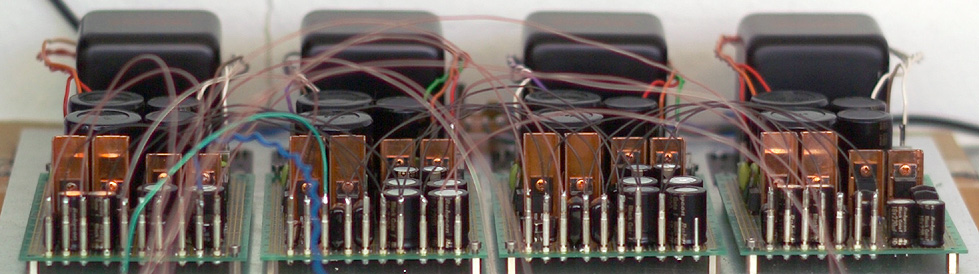
... mine is bigger than yours ...
Please count the heatsinks
14 shunt regulated rails for the DAC share the voltage reference and the driver rails that are provided by the additional two shunt regulators.
Those two shunt regulators together with the voltage reference form a secret system wherein the regulators provide the clean rails for the reference IC and its own driver stages, while the reference IC provides the stable reference voltages for its own shunt regulated supply.
Excuse the messy wiring, it is still a (working) test setup.
Hurtig said:
In total we have 14 regulators on-board!
Please count the heatsinks
14 shunt regulated rails for the DAC share the voltage reference and the driver rails that are provided by the additional two shunt regulators.
Those two shunt regulators together with the voltage reference form a secret system wherein the regulators provide the clean rails for the reference IC and its own driver stages, while the reference IC provides the stable reference voltages for its own shunt regulated supply.
Excuse the messy wiring, it is still a (working) test setup.
anli said:I don't understand the thread intention (except for "hey, we are great!") as long as the schematics is hidden. Do you? Are all those common words about "right way" new for anybody?
those common words are called "sales pitch" , check the ESS thread for more , so adorable...

Hurtig said:
In the analog stage, we use a special combination of a current source followed by a shunt regulator. This allows us to NOT have any capacitors decoupling the analog power rails.
Well, I find that a bit questionable, somehow.
What are the bandwith and impedance specs of your shunt regulators ?
microcontroller help me I am from Brazil.
hello friends .. sorry bothered you.
I am from Brazil and here is the end of the world when it comes to rotary encoders and LCD display.
ae I seek you aqui.desculpa the mistakes most do not speak the language of you turn to me here with a translator online.
wanted a project to control audio
which has a display on LCD display and volume control of the rotary encoder
ae someone have any schema.
and the code of the microcontroller for me.
may be a link.
Cauhtemoc said:It looks very well made. I can't say I agree with your choice of SPDIF receiver and DAC, but it's very well made nonetheless.
Thanks a lot!
The choice of reciever is practically done by the industri and not by us, as the CS8416 simply is the industri standard.
The only real alternative is CS8420 which is the same but with internal ASRC, which we did not want to use in our design.
The DAC chip itself is chosen because it is a state of the art component. We experimentet with several others from BB, but these need an I/V conversion stage, which complicates the design further. And by all means the DAC already contains more than 270 components on the PCB. An additional I/V stage is already designed, but we considered the pro´s of Burr Brown PCM1794A to be minor to the drawbacks of the I/V stage.
Therefore the Crystal chip was chosen, as we do not see any competitive alternative to that on the market by now.
The Burr Brown though has a very nice digital filter on board, and it is practically quantization noiseless. The CS 4398 does need a bit of filtering as there is some quantization noise above about 350 KHz.
anli said:I don't understand the thread intention (except for "hey, we are great!") as long as the schematics is hidden. Do you? Are all those common words about "right way" new for anybody?
I think this design is simply to complicated for the majority of DIYérs. There is simply a lot of posibilities to get in trouble mounting the board. First of all it almost completely SMD, next it needs sophisticated heat transfer to not grow to hot because of the shunt regulators, the third reason is that there only exists a diagram for the original construction not containing shunts.
Hope you understand!
Impressing Work - schematics
Very impressing result;
to get an impression how the machine works, how it handles time and finally how it may sound: will you share the schematics?
Maybe it would be interesting to compare your work on the CS4398 in its concept to that one: http://hoer-wege.de/dac4398.htm
for sure the ladder is a fully commercial project of an experienced DAC-Designer; but often the little punch of enthusiasm comes to a better result, because there was maybe not the necessity to get early bucks for the work.
In such a comparison your concept may build an interesting contrast to the well known OP-Amps driven analogue stage....
....no OP-Amps sounds quite interesting!
So are you willing to share your schematics?
so far
suchtgutenklang
analog_sa said:If you do intend to manufacture and sell to diyers make sure the digital and analogue boards are separate. This is obviously a compromise but i can't honestly see many orders for the digital part. And no, most of us do not believe "that the actual DAC-chip isn't that critical".
Well none of us really know if this DAC design are to be produced in small numbers or not.
So far we only made the one on the picture and in addition we do have a very worn out PCB containing the prototype.
Prototyping has by the way been the work has been done. Every single step has been discussed and tested, so that experience on every matter could be isolated as thorough as possible.
I.e. how does electrolytics behave and so on.
The digital section is not on a seperate board, because we belive en short signalpaths and an unbroken groundplane, therefore all is on one boardexept transformers, which have their own PCB (not shown).
Btw. of course the DAC chip is a very important component and as such the performance of the complete DAC is pretty much depending on the DAC chip. But what was ment was, that it is possible to reach good performance with most high end DACs, it just takes a lot of attention optimising the surrounding circuitry.
By that I mean filters, PSU´s, shielding, loads, decoupling etc.
The Crystal DAC is thus not chosen as a compromise, but was chosen because of the following reasons:
The 4398 does not need an additional I/V conversion stage.
There is at this point no other V out chip with better specs on the market.
We did already research the Burr Brown chips without really gaining better performance even with our discrete designed I/V converter.
Real world use of the fine specs of i.e. PCM1794A is very difficult as the output current is more than 15mA in monomode, which calls for i.e. NE5534AN opamps for I/V conversion, and we definately did not want to do that.
Analog Devices is no better, but stil nice.
Wolfson is a cheap alternative, but out of the question.
AKM is an even more inexpensive solution, but the specs are not as good as CS4398.
That leaves us just about Crystal Semi and very few others which are more or less unavailable for DIYérs.
The CS4398 is actually the successor of Philips high end DAC chips TDA 1547 which we happen to like pretty much i.e. in the Alchemy implementation.
We are actually very fond of the CS4398´s performance.
Now the specs does not necesarily mean better or worse perfomance, but we have at other ocasions listened to equipment including some of the discarded DAC chips. Naturally this did influence our choice af chip.
In the beginning our opinion were "Burr Brown and all the others" but as we came along, it did alter somewhat. Still we think that BB is in the top 2 or so, but their flagship DACs has the drawback of needing external I/V converters.
CS 4398 is a natural V out chip as it is a switched capacitor DAC and filter.
Bernhard said:
Well, I find that a bit questionable, somehow.
What are the bandwith and impedance specs of your shunt regulators ?
Hey there Bernhard!
As you do - I did!
I was actually not verry eager to try these shunts, of no other reason than "what I heard with shunts did not please me"
But Hurtig insisted, and I was extremely tired of composing a PSU, that had no sound of its own.
Actually the alterations in that proces shall be counted in hundreds - I spoiled aluminium electrolytics of diffrent makes in large numbers, as I did with bypass capacitors from various vendors.
The shunt wasn´t at all perfect in the beginning, but later on I started to apreciate it for its non colorating behavior.
The bandwith of the shunt should be around DC - 10 MHz and the output impedance somewhat below 0,5 milliohm DC - to around 10 MHz.
But the best feature is the noise level, the preregulations supresses ripple with around 60 dB, the shunt ads on a lot more. So theoretically the ripple should be supressed by just around 150 dB. If that is possible in real world electronics I do not know, but a lot less would be sufficient in this matter. Btw. the performance of the complete DAC does exactly feature an, to me, former unknown lowlevel reproduction. That means that "black backgound" has never been a succescriteria of this DACs performance, instead you always hear musicians being there doing something, even if it´s just breathing or if they i.e. recieve messages in their headphones or so.
'this design is simply too complicated for the majority of DIYérs'
Sorry;
but if you have this opinion, why are you posting in a DIYers-audioforum ????....I cannot really understand this
So I think anli is right :
...sorry again, but then things seem to become 'idle talk' without any reasonable basis on which an exchange of thoughts can take place...
...but that way the result for me especially is: looks nice, respect for that piece of craftsmanship, ...but so what...at least the hope that you may listen to music in an outstanding way!
proposal:
please provide for download two pictures in high resolution from both pcb-surfaces (or four: a) mounted b) unmounted)...would be clearifying things I guess
so far
suchtgutenklang
Kurt von Kubik said:
I think this design is simply to complicated for the majority of DIYérs. There is simply a lot of posibilities to get in trouble.....
Sorry;
but if you have this opinion, why are you posting in a DIYers-audioforum ????....I cannot really understand this
So I think anli is right :
anli said:I don't understand the thread intention (except for "hey, we are great!") as long as the schematics is hidden. Do you? Are all those common words about "right way" new for anybody?
...sorry again, but then things seem to become 'idle talk' without any reasonable basis on which an exchange of thoughts can take place...
...but that way the result for me especially is: looks nice, respect for that piece of craftsmanship, ...but so what...at least the hope that you may listen to music in an outstanding way!
proposal:
please provide for download two pictures in high resolution from both pcb-surfaces (or four: a) mounted b) unmounted)...would be clearifying things I guess
so far
suchtgutenklang
Re: Impressing Work - schematics
Thank you for your nice words
As already mentioned!
The documentation of the complete DAC is not yet present, thus you cannot have it.
Hifiwerkstadt did make a digitally ambitious project.
But we don´t really fancy op-amps at all, especially because they mostly need more than 100 dB of negative feedback.
We don´t belive in the "glorious" upsides of feedback, and it is actually as simple as that. Our analog stage is completely free of NFB - even in the power supplies regulations there is no NFB, and so be it.
We find a lot of extra low level information this way, as we do find unstressed and effortless soundreproduction. So it is crucial to us not to implement any NFB, RK transformers and electrolytic capacitors where it can be avoided.
We like straight forward design very much
suchtgutenklang said:Very impressing result;
to get an impression how the machine works, how it handles time and finally how it may sound: will you share the schematics?
Maybe it would be interesting to compare your work on the CS4398 in its concept to that one: http://hoer-wege.de/dac4398.htm
....no OP-Amps sounds quite interesting!
so far
suchtgutenklang
Thank you for your nice words
As already mentioned!
The documentation of the complete DAC is not yet present, thus you cannot have it.
Hifiwerkstadt did make a digitally ambitious project.
But we don´t really fancy op-amps at all, especially because they mostly need more than 100 dB of negative feedback.
We don´t belive in the "glorious" upsides of feedback, and it is actually as simple as that. Our analog stage is completely free of NFB - even in the power supplies regulations there is no NFB, and so be it.
We find a lot of extra low level information this way, as we do find unstressed and effortless soundreproduction. So it is crucial to us not to implement any NFB, RK transformers and electrolytic capacitors where it can be avoided.
We like straight forward design very much
- Status
- Not open for further replies.
- Home
- Source & Line
- Digital Line Level
- DAC project completed