Coax is connected to switch
Coax is connected as well even though the schematic doesn't show any of this. To leg 14 of the switch but it doesn't work. I will have to disable the optical and swap pins.
.
Coax is connected as well even though the schematic doesn't show any of this. To leg 14 of the switch but it doesn't work. I will have to disable the optical and swap pins.
.
Aha! You found it. The problem is it switches between opt and USB. You will have to convert one of those to coax if that's what you want, or add an external mux.
It's not an opamp, it's an inverter/buffer.
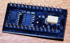
DIR9001 photo
I have verified that riser pin 4 from the coax is connected to leg 14 of the switch and both riser pins 10 and 11 for SA and SB are set to ground as they should be but the receiver will only lock to the optical. My SRC2496 and DEQ2496 have optical outs so I can supply an optical for now until I figure out how to fix it or just start using a hard wire instead of the switch. The item on the left is the switch. The other IC is the buffer.
I have verified that riser pin 4 from the coax is connected to leg 14 of the switch and both riser pins 10 and 11 for SA and SB are set to ground as they should be but the receiver will only lock to the optical. My SRC2496 and DEQ2496 have optical outs so I can supply an optical for now until I figure out how to fix it or just start using a hard wire instead of the switch. The item on the left is the switch. The other IC is the buffer.
Attachments
received the opa2107s today. plugged them and wow, notice a huge improvement. the dac is now smooth and organic. tubey enough to put the lite dac 60 to the shame if the prices are mentioned. however the trebles are still overemphasized. i suspect the culprit to be the sanyo os-cons that i got offered from the seller as an upgrade. in another thread, they are described as sharp sounding when used in analogue circuit. since i'm completely new at this, which are the caps in the analogue circuit of this dac? are they the last 4 that are lined up before the 1st op-amp? if so, my solder is ready...
thanks, Bill. so are those four all there is in the analog circuit? also my dac came with 13v+13v EI transformer. but i realize that the dac only requires 7-10v on the digital circuit as it is clearly stated on the board... i have the opa1798 version though. would that be why it's different?
p.s. still waiting on the info of how to bypass the op-amps on 1798 board. also, i apologize for acting as though this is a FAQ thread. perhaps i should've come here once it was 600 pages long.
p.s. still waiting on the info of how to bypass the op-amps on 1798 board. also, i apologize for acting as though this is a FAQ thread. perhaps i should've come here once it was 600 pages long.
PCM1794a mono
Would running a pair of PCM1794a in mono mode double the available current output? If so this might bring the required transformer gain down to where you might get by with 1:2 depending on how much level your amp really needs to achieve a high listening level opening up more options for affordable transformers.
.
There are two different things in your post:
first, I think Kevin suggested 5k at the transformer secondary for the 1798 (3k for 1794 if I do remember) like they do in their passive stage output for the Rakk dac (take a look at the K & K website for the connections).
about my setup, nothing else has to be done on the adaptor board other than you see on the picture and explained in an earlier post. I ordered first an adaptor 1798 board and stripped all the unwanted parts to make the job easy.
Now for IV conversion I prefer for the moment (sonic taste) to load the LL1674 (and that was the same for UTC A20) at the primary. One 220R at each transformer input all wired to the ground. That said, maybe I will try later to load the secondary with different types of resistor.
thanks, Bill. so are those four all there is in the analog circuit? also my dac came with 13v+13v EI transformer. but i realize that the dac only requires 7-10v on the digital circuit as it is clearly stated on the board... i have the opa1798 version though. would that be why it's different?
p.s. still waiting on the info of how to bypass the op-amps on 1798 board. also, i apologize for acting as though this is a FAQ thread. perhaps i should've come here once it was 600 pages long.
It's pretty hard to find stuff in this thread now.
If you're using the opamp section you need the 13v trafo. If you're just using the digital section all you need is the 7v or so.
I don't know what the 1798 board uses for power, I don't have one.
thanks, Bill. so are those four all there is in the analog circuit? also my dac came with 13v+13v EI transformer. but i realize that the dac only requires 7-10v on the digital circuit as it is clearly stated on the board... i have the opa1798 version though. would that be why it's different?
p.s. still waiting on the info of how to bypass the op-amps on 1798 board. also, i apologize for acting as though this is a FAQ thread. perhaps i should've come here once it was 600 pages long.
The PCM1798 still needs both 5V (DAC analogue section) and 3.3V (DAC digital section) supplies to operate like any DAC chip. The LM317 regulators need a few volts headroom (dropout) to operate properly so as long as you give them at least 9V supply thats fine. Anything above that is dissipated as heat. You could give them 25V and they would only regulate to 5V but get very hot.
Would running a pair of PCM1794a in mono mode double the available current output? If so this might bring the required transformer gain down to where you might get by with 1:2 depending on how much level your amp really needs to achieve a high listening level opening up more options for affordable transformers.
.
I don't think it works like that. Using PCM1794 in dual mono doesn't double the output, it just uses one chip for each channel. Each channel still has the 7.8mA output current that the 1794 provides.
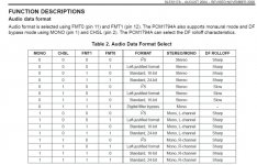
mono
The chips are usually used with L+, L-, R+, and R-. By selecting a mono mode, which is one of settings available in the registers, you can get L+, L-, L+, and L-. You may need to add a small, well matched series resistor, like 2 ohms or smaller (maybe none), to each output to keep one or the other from power hogging, but the signal will be well correlated in the audio band so you should be able to parallel each pair for 15.6ma which should get the transformer requirement down to 1:2. The SPDIF can simply be shared (re-terminate to get 75 ohms if you like) between two boards with one chip set to left and the other set to right channel.I don't think it works like that. Using PCM1794 in dual mono doesn't double the output, it just uses one chip for each channel. Each channel still has the 7.8mA output current that the 1794 provides.
Attachments
two boards
.
K & K Audio - Lundahl Transformers, audio DIY kits and more
.
Too bad these Edcor trannies are a little too small. 80% nickel core and center tapped for only $26 vs $130 for an amorphous Lundahl.
.
EDCOR - Browse Series
We should just be able to work with two stock Gigaworks boards to start. Either the big dac boards, or the the newer small dac boards if you don't want a DIR9001 or upsampler option. Just split the coax spdif with a "Y" cable as I have done with two DCXs without consequence and do the mods to set the registers to mono and create the parallel, transformer I/V mod. This should also work with the PCM1798 to get the output up and suitable for the 1:4 Lundahls that Rakk dac uses with a stereo 1794.this would be very interesting.
I take it you would need to custom design a PCB to mount the two chips (vero board?) If you can work this out, definitely share the layout.
Rich
.
K & K Audio - Lundahl Transformers, audio DIY kits and more
.
Too bad these Edcor trannies are a little too small. 80% nickel core and center tapped for only $26 vs $130 for an amorphous Lundahl.
.
EDCOR - Browse Series
Stacked Mono mode PCM1794a
It might even be pretty easy to mod the stock PCM1798 module boards to stack one on top of the other in order to try mono mode with a passive I/V. Soldering another set of sockets onto the top of one board would be a piece of cake.I take it you would need to custom design a PCB to mount the two chips (vero board?) If you can work this out, definitely share the layout.
Rich
Next thought stacked
Then my next thought is. Do we need to select mono mode at all or would stacking two stock 1798 (or 1794) boards double the current output with no other mods?It might even be pretty easy to mod the stock PCM1798 module boards to stack one on top of the other in order to try mono mode with a passive I/V. Soldering another set of sockets onto the top of one board would be a piece of cake.
Long time no speak. At last I'm back onto my DAC project. Before I get on with more mods (power supply), I want to make sure what I already have is correct and would be grateful for some info;
1) What are the audible symptons of magnetised output trannies?
2) Is my anti-ringing filter ok? I have 1000pF cap + 1K resistor in series, soldered across RCA + & - terminals (circuit diagram is here - hoverdonkey's DAC - DIY DAC).
Thanks
1) What are the audible symptons of magnetised output trannies?
2) Is my anti-ringing filter ok? I have 1000pF cap + 1K resistor in series, soldered across RCA + & - terminals (circuit diagram is here - hoverdonkey's DAC - DIY DAC).
Thanks
Datasheets etc
I have pooled together some of the datasheets etc relating to this board.
Enjoy;
Intro/Datasheets - DIY DAC
I have pooled together some of the datasheets etc relating to this board.
Enjoy;
Intro/Datasheets - DIY DAC
Hey, how ya doin?
Looked at your dac, was really surprised. My GA80080s are open frame, that's weird.
The filter's still good. If you drop down to around 250 ohms on the primaries it will give you a little more bass reach if you need it.
Nice collection of info, did you see the posts about the incorrect voltage feed on the upsampler board?
- Home
- Source & Line
- Digital Line Level
- Experience with this DIY DAC ?