Yep, can't get this to work properly. I tried two PCM assembly's one with op-amps and decoupling components and one without. The result was the same with both - very low volume and loud hiss. I also tried Bill suggestion of removing the secondary resistor and also tried without resistors on primary leads.
The UTC's are basically unsuitable for current output DAC's. However the PCM1794 has higher output than the 1798 so might try that sometime. I will shelve the project until I can afford appropriate output transformers.
McGyver - out of interest, which transformers and tube stage did you use?
Cheers
Rich
How did you connect the 47R on Primary?Between primarys or primary to ground?McGyver, that looks very nice.
I am trying the PCM1798 in my DAC now but have very low volume and hiss. It may be the UTC A-20's I am using, although I have them configured for 1:3 with 47R resistors on primaries and 510R across secondaries.
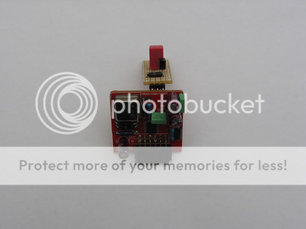
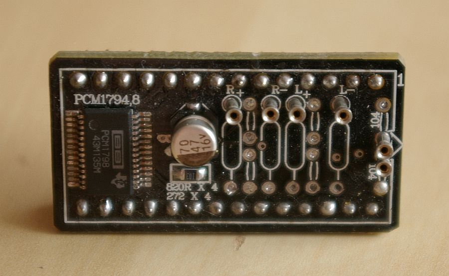
Did you remove the opamps under the PCM adapter? I think I may need them for adequate signal amplification. The spec calls for OPA2604 but I have some OPA2132 and OPA1642 I could try. I ordered blank adapter boards from snow and used some sample PCM1798 DAC chips. I have 56uF oscon and 10K resistor similar to your board in post #2854.
Any ideas?
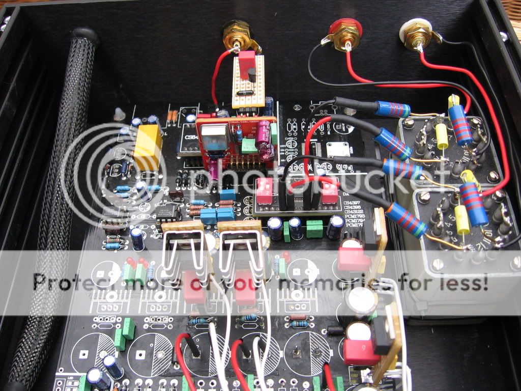
I should add that the DAC is sounding very good indeed with CS4398 chip following some extensive modifications recently.
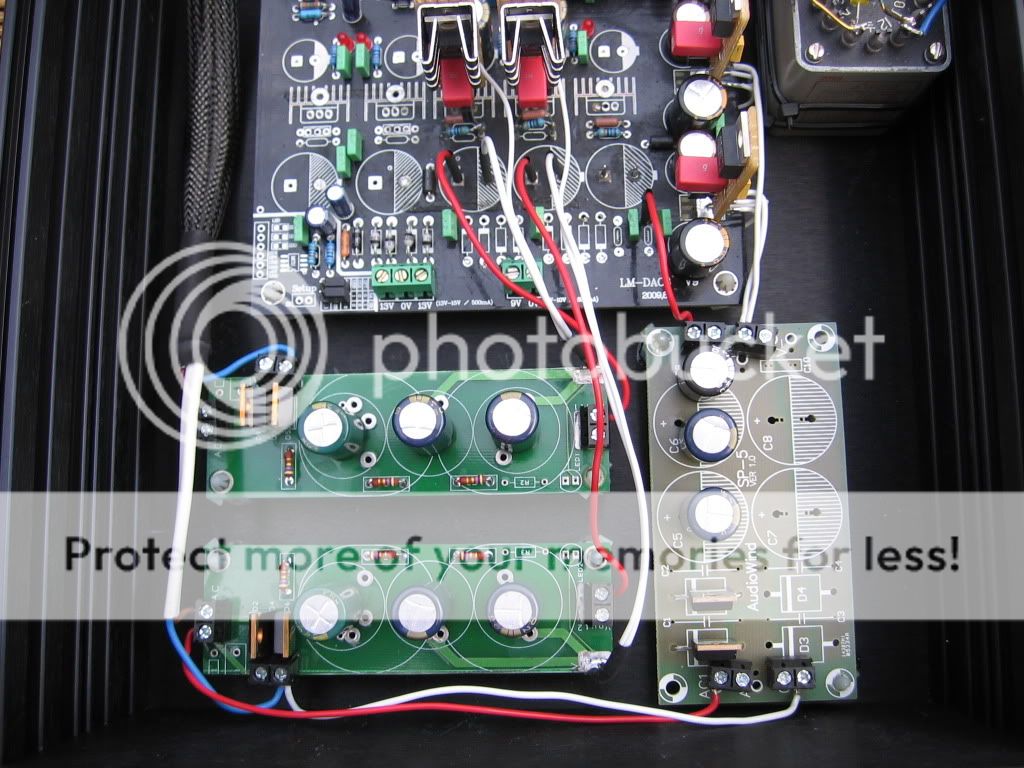
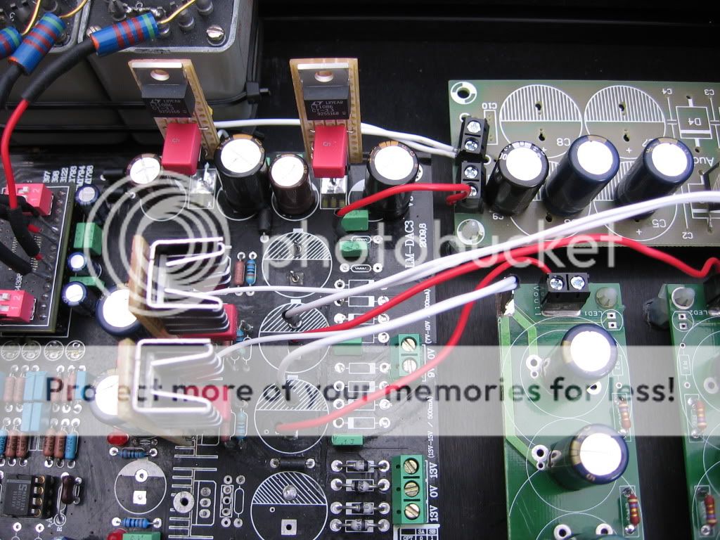
I upgraded and separated the power rails for 5V and 3.3V digital rails and added VBE 'Regulator boosters' made on strip board to all supplies including the up-sampling module. I intend to try a PFM flea module for the sampling clock XO module and separate 3.3V regulator for the CS8421 sampling chip. I would also like to try a DIR9001 with a flea regulator supplying the onboard XO clock.
Some pics:
How did you connect the 47R on Primary?Between primarys or primary to ground?
Ryssen I had 47R on each primary!
Was this wrong?
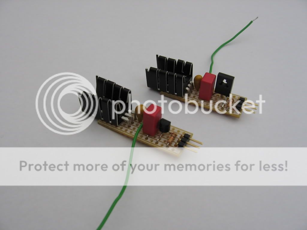
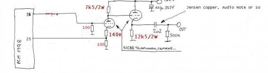
I used some Sowters 1:10 or so, but I don't have it any more and don't remember the symbol.
My tube stage is like this:
Thanks Mcgyver, the tube stage looks nice and simple. I could bravely attempt that sometime. Could you post some pics and component values. I really like your DAC case is it a Modushop?
I had considered Sowter, not least as they are in the UK, something like the 9762 model.
Cheers
Rich
I used some Sowters 1:10 or so, but I don't have it any more and don't remember the symbol.
My tube stage is like this:
Too complicated!

Too complicated!
Yep, it uses more than three components... its out of my league!
")
Mcgyver, would you need separate power supplies for filament and heaters etc?
What do you mean? Filament=heaters.
Sorry, I'm quite inexperienced with tube designs.
For instance with the Aikido and Andrea Ciufolli's DAC-end designs, there is two supply rails: one 12V for the tube heaters and one larger one (200V) for, i think, the filament. I could be wrong. I'm just wondering if your tube stage needs any form of additional power supply. I'm guessing at least 12V for ECC88 (6922) type tubes.
For instance with the Aikido and Andrea Ciufolli's DAC-end designs, there is two supply rails: one 12V for the tube heaters and one larger one (200V) for, i think, the filament. I could be wrong. I'm just wondering if your tube stage needs any form of additional power supply. I'm guessing at least 12V for ECC88 (6922) type tubes.
Ryssen I had 47R on each primary!
Was this wrong?
Yes,from each primary winding to ground?I havent tried my PCM1798 yet but I was advised to try with 120 ohms resistors,I think (if I´m not wrong) that will give a larger signal than with 47 ohm.
Ok Ryssen, just to clarify -
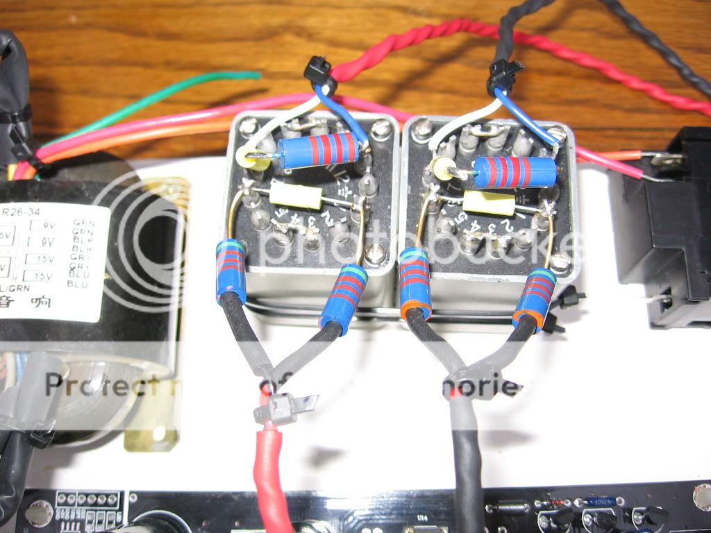
When you say "from each primary winding to ground" do you mean that the primary leads are attached to the output pins on the DAC adapter and the resistors go from the pins to signal ground.
Not, like previously, the resistors are in series with the leads to the transformers, like here:
And you are using no resistors across secondaries?
Those resistors seems to be in series,they should be to ground,as the PCM1798 is a current output DAC it needs the resistors to ground to generate a outputsignal across them from the current.So remove the resistors,connect the wires directly to the trafo and from each wire a resistor to ground.The resistor and cap at seconary is a filter and should have nothing to do with this so leave them there.
Thanks Ryssen. Yes the pic above is of my old setup and used as an example of what not to do!
Thanks for the advice.
Two more questions:
I suppose it matters little if the resistors are connected at the DAC end or transformer end - to ground.
Would a suitable ground be to return to the power supply 0V or find a nearer one to the DAC?
Thanks for the advice.
Two more questions:
I suppose it matters little if the resistors are connected at the DAC end or transformer end - to ground.
Would a suitable ground be to return to the power supply 0V or find a nearer one to the DAC?
- Home
- Source & Line
- Digital Line Level
- Experience with this DIY DAC ?