Lampucera mini DAC
Hi, I found Lukasz Fikusz's pages approx 4 months ago. There are many interesting stuff over there, and I decided to give a try to "Lampucera 1.0" project (because of the cheapest one). After a while, I found this forum, and I am really amazed about this thread too! So, I bought a mini DAC board only, and upgraded the smd parts. The sound of the DAC is great: smooth, lovely, dynamic. The full symmetric version is even better! I steal the signal from L-, L+, R-, R+ points, followed by GE 330 nF/850 V capacitors. The signal goes to a Balanced Bride of Son of Zen preamp (DIY") . The power source is an 6 V SLB (Sealed Lead) battery with special circuit. The black labeled was made to my friend; the red substitutions are for my version. János
. The power source is an 6 V SLB (Sealed Lead) battery with special circuit. The black labeled was made to my friend; the red substitutions are for my version. János
Hi, I found Lukasz Fikusz's pages approx 4 months ago. There are many interesting stuff over there, and I decided to give a try to "Lampucera 1.0" project (because of the cheapest one). After a while, I found this forum, and I am really amazed about this thread too! So, I bought a mini DAC board only, and upgraded the smd parts. The sound of the DAC is great: smooth, lovely, dynamic. The full symmetric version is even better! I steal the signal from L-, L+, R-, R+ points, followed by GE 330 nF/850 V capacitors. The signal goes to a Balanced Bride of Son of Zen preamp (DIY
. The power source is an 6 V SLB (Sealed Lead) battery with special circuit. The black labeled was made to my friend; the red substitutions are for my version. JánosAttachments
I see. In that case I'll try without the R. Hopefully I'll notice an improvement.
Theoretically - if I placed one(trafo) on my source(Squeezebox) would the one on the DAC then become redundant? If so I might just remove it and move it over to the SB.
Hi McCrackers,
From everything I read and recent experience, it probably is redundant. I haven't added a trafo to mine but I have added buffers and trafos to my CD sources outputs to great results. It,s a little OT but reclocking the SPDIF output of the player is a much greater improvement than I ever expected.
Hi Bill,Hi McCrackers,
From everything I read and recent experience, it probably is redundant. I haven't added a trafo to mine but I have added buffers and trafos to my CD sources outputs to great results. It,s a little OT but reclocking the SPDIF output of the player is a much greater improvement than I ever expected.
Wouldn't happen to be a step by step for this procedure anywhere - would there? I don't want to discourage anyone, as the way I have it configured might be responsible, but I've come to the conclusion that the audible benefits achieved with the implementation of a pulse trafo on the DAC's input are marginal at best. However I did read some discussions on other forums(such as this one) where people seemed to be really satisfied with the results. I guess it's a YMMV thing.
Last edited:
Hi Bill,
Wouldn't happen to be a step by step for this procedure anywhere - would there? I don't want to discourage anyone, as the way I have it configured might be responsible, but I've come to the conclusion that the audible benefits achieved with the implementation of a pulse trafo on the DAC's input are marginal at best. However I did read some discussions on other forums(such as this one) where people seemed to be really satisfied with the results. I guess it's a YMMV thing.
Actually, there is a generic step by step for reclocking at Tentlabs website. The installation instructions for their XO2 and XO3 modules is available. You have to replace the clock in the player then pass the SPDIF signal through a 74hc74 then through a pulse trafo. It's a little complicated to cobble the circuitry together but if you use a unit like the XO3 module it's cake, although the XO3 costs more than the dac were using.
As far as audible improvements from using a pulse trafo, I cant see how it could improve anything except possibly better impedance matching. I still think less is more unless there is a real need.
As a matter of fact - as we speak the DAC is playing without the trafo and as much as it hurts me to say so - I would have to agree with that.
I might like to give the clock mod a go. Can this be done on an SB3?
What are the voltages on this DAC board (except for the opampvoltages).
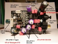
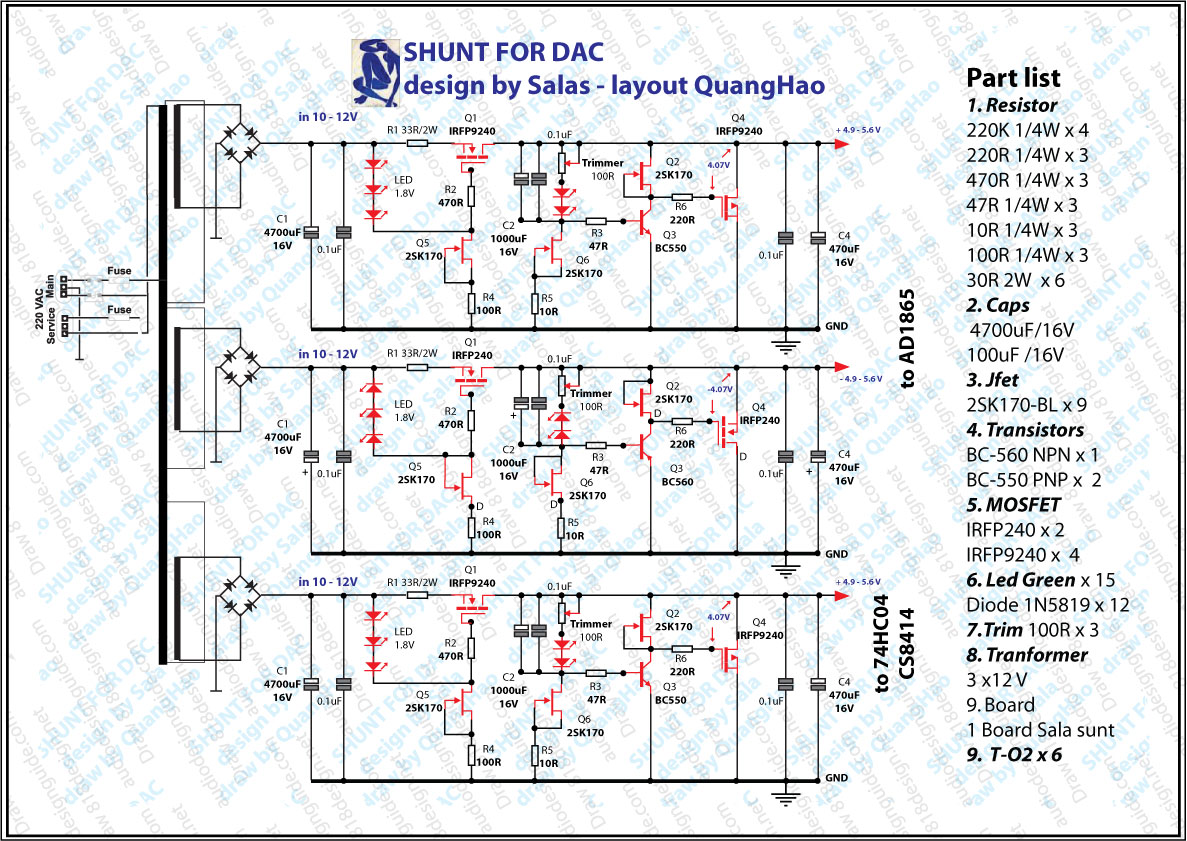
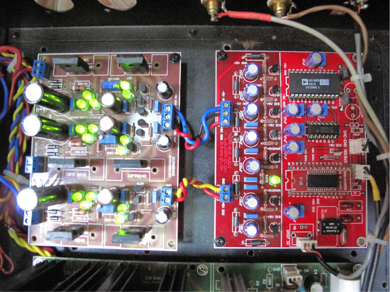
I thought of using quanghao´s shunt reg board http://www.diyaudio.com/forums/attachments/group-buys/148752d1259719287-dac-end-andrea-ciuffoli-group-buys-sala-shunt-
dac.jpg
http://www.diyaudio.com/forums/attachments/group-buys/150314d1260860579-dac-end-andrea-ciuffoli-group-buys-dong-dien.jpg
Group Buy:http://www.diyaudio.com/forums/group-buys/155960-dac-end-andrea-ciuffoli-group-buys.html
It has an output of +5v -5v and +5 volt,vould it be possible to use it for the DAC part?
What are the voltages on this DAC board (except for the opampvoltages).
I thought of using quanghao´s shunt reg board http://www.diyaudio.com/forums/attachments/group-buys/148752d1259719287-dac-end-andrea-ciuffoli-group-buys-sala-shunt-
dac.jpg
http://www.diyaudio.com/forums/attachments/group-buys/150314d1260860579-dac-end-andrea-ciuffoli-group-buys-dong-dien.jpg
Group Buy:http://www.diyaudio.com/forums/group-buys/155960-dac-end-andrea-ciuffoli-group-buys.html
It has an output of +5v -5v and +5 volt,vould it be possible to use it for the DAC part?
Definitely yes....besides the regulator meant for preamp and dac....but the board itself is too big to put into the chassis....
probably i'm thinking another shunt board like this reg-v2n-5d_shunt_regulator_PCB
I just wondering to those who applying output traffo mod such as Lundals, UTC and others, what else that you can do from here...? Would it be a tube output after the traffo...??? Is this the ending for this DAC board.....???
I imagine some will try upgrading the PS with shunt regs. A tube buffer circuit after the trafos, or a jfet buffer like the Pass B1.
I'm thinking about feeding I2S from a transport directly to the upsampling chip to eliminate the clock reconstruction in the CS8416.
I've been working on improving the SPDIF quality with surprising results so eliminating it should be quite a step up.
Bill,
Is it possible to extract I2S from any kind of CDP...? I heard you have to add up some kinda modules to do that and mostly a diy transport....correct me if I'm wrong....besides this part is getting technically delicate for a novice diyer...IMHO
Yeah, it's gonna take some time figuring everything out. I'm not a digital tech by any stretch.
I2S is available from the Philips transports, the Japanese use other formats AFAIK. I believe the upsampling chip is universally compatible with all formats, but I could be wrong.
I have several CDM4s, I like them very much.
You should be able to find the data stream in any player and determine what it is by looking at data sheets for the chips used. Takes a little detective work.
Yeah, it's gonna take some time figuring everything out. I'm not a digital tech by any stretch.
I2S is available from the Philips transports, the Japanese use other formats AFAIK. I believe the upsampling chip is universally compatible with all formats, but I could be wrong.
I have several CDM4s, I like them very much.
You should be able to find the data stream in any player and determine what it is by looking at data sheets for the chips used. Takes a little detective work.
Hope it can be done in CDM12...
I think the closest mod that can be done right now is the regulator and the final tube stage....I've seen one DAC with such mod done by Mcgyver
Notice that in Andrea Ciuffoli's DAC END circuit, there's a lot that can be implemented to the CS board although AD is a current DAC...look at the +5v and -5v circuit for the DAC. Using LD1086V50 is simple enough for the digital section PSU for the DAC and maybe better that generic LM7805 regulator and small too....
Andrea use E182CC which is pretty much the same to 6H6P used for lampizatior and we can use the PSU circuit for anode and heater supply...
But which is first and latter...tube followed by the output traffo or the other way around....
Andrea use E182CC which is pretty much the same to 6H6P used for lampizatior and we can use the PSU circuit for anode and heater supply...
But which is first and latter...tube followed by the output traffo or the other way around....
Don't use SRPP as a tube stage for CS4397 unless you want about 20V signal level at output.
Then we can use cathode follower instead SRPP after the output trans....put some big input/output cap....
- Home
- Source & Line
- Digital Line Level
- Experience with this DIY DAC ?