fredlock said:Linuxworks, That's awesome!!!
Those are really neat features. Would you be so kind to share that info to us, to create one for ourselves? I like that big LCD display. How much dit it cost you?
it was somewhat cheap, in the $30 range at mouser or digikey. I got it by mistake, actually
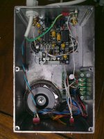
") I thought I was getting a standard 4x20 size but with a really thin amount of pcb 'frame' around it. it looked like a good standard lcd to fit into small places. ha, was I wrong it was thin framed, alright, but supersized. needs 4 leds (you can see them) as backlights. its still 5v backlight so the arduino PWM pin talks to it directly, just fine. I'll find the part # for you when I get a chance, but its findable at mouser or places like that. newhaven was the manuf and its the usual 16 pin hitachi interface, nothing hard at all about it. no graphic mode other than normal hitachi '8 gfx chars' and that's it. still, I got usable 'meters' for song length and for volume level just from those 8.
I thought I was getting a standard 4x20 size but with a really thin amount of pcb 'frame' around it. it looked like a good standard lcd to fit into small places. ha, was I wrong it was thin framed, alright, but supersized. needs 4 leds (you can see them) as backlights. its still 5v backlight so the arduino PWM pin talks to it directly, just fine. I'll find the part # for you when I get a chance, but its findable at mouser or places like that. newhaven was the manuf and its the usual 16 pin hitachi interface, nothing hard at all about it. no graphic mode other than normal hitachi '8 gfx chars' and that's it. still, I got usable 'meters' for song length and for volume level just from those 8.an arduino chip can be as little as $5 and $1 for the xtal or cer-res. the ethernet module is a 'wiznet' thing that has somewhat usable arduino driver support (actually, trivial to open a remote web connection and send/receive data, which is what I wanted). the ethernet module is in the $25 range, so I guess that's one of the most expensive parts, here
the firecracker stuff was a joke, at first; but now I like it
it lets me turn on and off things, so I could switch between a spkr amp and a headphone amp by putting them on 2 diff house-code/unit-code settings and then designing the software so that when I press diff IR remote buttons, it 'closes down' one device (spkr amp) and then 'starts up' the other one (phones amp), all in concert, as they say its just C code, in arduino 'sketch' format.yes, I'll be releasing the code and DIY plans. its still in alpha and its still a moving target, so until things settle (I have at least 1 more module to complete) it will be photos-only
I'm hoping to get that other module designed, tested and software integrated in the next couple of weeks. hopefully.so far, though, the whole combo is quite usable. its a single box that does almost all I need for my home stereo needs. this and a companion amp have replaced my 'yamaha avr' box that did some of what I wanted, but never quite all
(sorry about the inline posting of images; I removed the literals and made them url's instead).
so far, I've only just 'integrated' this dac, I have not even started doing the various audio tweaks first, get the thing in a test bed (now complete) and then mess around with it (lol).
the relay is annoying the hell out of me, though ;( on one of my sources (popcorn hour) the relay clicks quite a lot as you play dvd's. the spdif from that device is quite wonky and this causes 'valid' to be on and off, which means the relay is on and off. grrr! this relay MUST be replaced (the mute relay). I think that's the very next mod I have to do.
so far, I've only just 'integrated' this dac, I have not even started doing the various audio tweaks
first, get the thing in a test bed (now complete) and then mess around with it (lol).the relay is annoying the hell out of me, though ;( on one of my sources (popcorn hour) the relay clicks quite a lot as you play dvd's. the spdif from that device is quite wonky and this causes 'valid' to be on and off, which means the relay is on and off. grrr! this relay MUST be replaced (the mute relay). I think that's the very next mod I have to do.
fredlock said:Linuxworks, That's awesome!!!
Those are really neat features. Would you be so kind to share that info to us, to create one for ourselves? I like that big LCD display. How much dit it cost you?
found it, it was from mouser:
NHD-0420E2Z-NSW-BBW (Newhaven Display)
Mouser Part #: 763-NHD0420E2ZNSWBBW
the bad news: its now non-stocked ;( to be honest, the un-evenness of the backlight was probably something that turned a lot of people off. I was thinking of returning mine, when I first got it. but its SO LARGE and useful for older eyes (mine) that it made such a usability diff in being able to SEE the song names, volume level and so on.
this company also makes RGB backlight displays (in 16x2) and I've played with them, they're cool as can be
I started doing some led RGB color mixing code in arduino-land and got lost in just that, for a few weeks great fun to be able to color map things or just color the display 'for fashion'. since this display is just 4 leds, I bet rgb leds could be put in there and used the same way as their factory stock RGB ones.McGyver said:
Cathode follower... You need two triodes, it's one tube. You need one power supply PCB with 2 or 3 caps and 2 output caps.
Mcgyver
can you answer a few more questions please,
1. regarding the 3 power caps, what uF, V do I need to get minimum and preferred.. and should I stick to 105c rather than 85c
2. on your power PCB I could not see a bridge rectifier is this not required ?.
3. regarding the Output caps are 2 Obbligato Film Oil 2.0uF 630V good for the job or is Obbligato Copper Caps a better choice (double price) what others that are readily available do you recommend that are not crazy expensive.
OBBLIGATO]Link to OBBligato Film Oil Cap
4. will any double triode do I.e 6h6p/6n6p or is this overkill, if so can you recommend others.
5. I found this power board on ebay that is already made up that will work out to about $8 more than buying parts & making it myself would this be sufficient or are the components on it rubbish or overkill as there 4 caps on board. If I do it myself I'll purchase the same bare board.
Power Board
6. how much power do I actually need to power the valve in case I see other board fully assembled.
Thanks
Shuggy67
about the caps, give a look to these capacitors they are straordinary and costs few penny
http://www.diyaudio.com/forums/showthread.php?s=&threadid=143675
about the caps, give a look to these capacitors they are straordinary and costs few penny
http://www.diyaudio.com/forums/showthread.php?s=&threadid=143675
shuggi67 said:
Mcgyver
can you answer a few more questions please,
1. regarding the 3 power caps, what uF, V do I need to get minimum and preferred.. and should I stick to 105c rather than 85c
2. on your power PCB I could not see a bridge rectifier is this not required ?.
3. regarding the Output caps are 2 Obbligato Film Oil 2.0uF 630V good for the job or is Obbligato Copper Caps a better choice (double price) what others that are readily available do you recommend that are not crazy expensive.
OBBLIGATO]Link to OBBligato Film Oil Cap
4. will any double triode do I.e 6h6p/6n6p or is this overkill, if so can you recommend others.
5. I found this power board on ebay that is already made up that will work out to about $8 more than buying parts & making it myself would this be sufficient or are the components on it rubbish or overkill as there 4 caps on board. If I do it myself I'll purchase the same bare board.
Power Board
6. how much power do I actually need to power the valve in case I see other board fully assembled.
Thanks
1. There should be good quality caps. I used Nippon-Chemicon.
2. You don't see not means there is no rectifier. Rectifier is indispensable.
3. Soviet teflon caps.
4. ECC88 or E88CC will do. 6N6P or E182CC fits too, even if it's a little overkill.
5. This power board is intended to feed transistor power amplifier. You can't use it for a tube stage.
It makes no sense to copy my circuit upon my pictures, you can't do it properly. I'll draw schematics and post it later.
So are Teflon caps better suited to the project than say PIO caps like the K75-10 or would a Teflon cap like the FT-3 be more suited, can someone also indicate what is the ideal uF and voltage I should be looking for as a minimum and optimum I thought about 1uF 160V minimum and 2uF 630V as a Max.
Cheers
Cheers
McGyver said:The voltage should be at safe level. If the tube stage is powered from 200V, then safe voltage of the capacitors is 250VDC.
Ahh got it, so I need to build or buy the power-board first to get an idea what power I'll need for the caps.
I'm still trying to find a suitable board with no luck, did you get a chance to draw a schematic of your power board to give me a rough idea.
Thanks
shuggi67 said:
Ahh got it, so I need to build or buy the power-board first to get an idea what power I'll need for the caps.
No. You need to know first what voltage needs the tube you're going to use. And then you get an idea what voltage must give your power supply. For example ECC88 needs about 90V, and 6N6P needs about 120V.
I'm still trying to find a suitable board with no luck, did you get a chance to draw a schematic of your power board to give me a rough idea.
Thanks
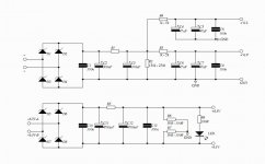
My power supply is something like that:
Attachments
data said:Well, I got this DAC working with these custom transformers, very transparent if a little bit shy down low.
Maybe I just need to adjust some R&C values. hmm...
Well Done. You'll have to fill us in on the trafos you used, ratio and DCR and such.
I found a small increase in bass when I went from 250R to 500R on the primaries, but the change to 1K didn't seem to make any difference.
I have my NOS A-22s in there now so I can A-B them against the Sescoms. The Sescoms still win but the margin is smaller than the Jensen JT123 comparison. Still, any of them beat my old setup (PCM63-discrete I/V) in resolution and organic texture.
Bill
I don't have any info on these tranfos, I just tried different loads on the primaries and secondaries.
They seem to need at least 50k on the secondaries that carry the signal.
Am I supposed to load the negatives on the secondaries too?
This is very difficult when not knowing the specs of the tranfos
They seem to need at least 50k on the secondaries that carry the signal.
Am I supposed to load the negatives on the secondaries too?
This is very difficult when not knowing the specs of the tranfos
If you want to do a little detective work you can measure the DCR with a 1K resistor in series with the meter to protect the trafo from possible saturation, then just subtract the 1K from your reading. The nominal impedence is generally 10 to 20 times the DCR so that will give you a ballpark impedence number. If the DCR comes out at 50 ohms or lower then they are probably 600 ohm, if it comes out to 100s or 1000s DCR then you have a high impedance trafo which does need a load resistor. Your secondary wiring should be completely isolated from everything and go directly to your RCA jacks, and your load or filter should go right across the output, pos to neg. There is no difference between them except phase, and either can be used as ground on the RCAs so long as you hook up both channels the same.
Best, Bill
Best, Bill
Question from an iTunes User
Hello folks:
Apologies in advance for not reading all 32 pages of this thread. I will, though. I promise.
I bought a Gigalab dac to turn my Mac Mini into a music server. (This is all a bit new for me.) I have it connected via USB, BTW.
I've burned a few CDs and one SACD to the drive in Apple Lossless format and took the DAC for a test drive. Everything sounds very nice, but I noticed a posting that said single speed sampling it optimal for playback.
If I set the DAC for single speed (00 or 01), there's no sound. It plays fine on double speed (10) and quad speed (11).
Any advice or suggestions on my configuration.
Steve
PS. I was immensely relieved to find a thread on this device.
- Home
- Source & Line
- Digital Line Level
- Experience with this DIY DAC ?