fordgtlover said:Sorry for the silly questions.
In legarem's diagram in post #418, the black wire is connected to the ground connection. Is that the analog ground of the DAC?
http://www.diyaudio.com/forums/attachment.php?s=&postid=1817093&stamp=1241223954
Also, on the same diagram, is the type of capacitor across the transformer primaries important (0.0047uF)?
Yes, it is connected on the analog ground
In my diagram, I forgot a 0 on the cap value. The good value is: .00047 uF not .0047 uF. Sorry.
If you keep the ,0047 uF, you can also change the 1K for 100 ohms and you'll get a lot more gain with the right cut off frequency.
The capacitor can be polypropylene, polystyrene, mica.
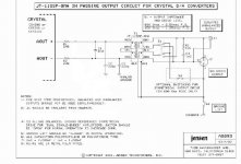
I had emali exchange with Bill Whitlock from Jensen transformers. Here is some interesting things related to the schematic included in this message:
1. The low-pass filters are used to supplement the characteristics of the transformer itself. Since the Faraday shield in the JT-11SSP-8MA (or any transformer with such a shield) functions well only below a few MHz, the two 220 pF capacitors and 249 Ω resistors function as a 3 MHz low-pass filter for common-mode to insure that RF energy does not interfere or cause strange intermodulation distortions in downstream equipment. The differential filter, consisting of the 2.2 nF capacitor and 249 Ω resistors, is set to be -3 dB at 160 kHz. This frequency is sufficiently high to add negligible phase distortion (that's deviation from linear phase, not phase shift) while low enough to control ultrasonic artifacts that can also cause strange distortions in downstream equipment (see the 1988 AES paper by Deane Jensen and Gary Sokolich for details on "Spectral Contamination").
2. The differential voltage across the transformer primary must be kept to an absolute minimum (<1 mV) to prevent a shift in the magnetic operating point of the core material. Any significant dc flow in the transformer will alter its distortion characteristics. Normal (for Jensen-selected core materials) transformer distortions consist almost entirely of 3rd harmonic, but adding a dc component creates a series of even-order distortion products (2nd, 4th, 6th, etc.).
Attachments
udovdh said:About the voltage across the primary: how?
The DAC chip has a certain offset.
Or will it be bear-zero? (no opamps)
As stated in a previous message, after modifying 6 of these dacs, there is always 0mv between the + and - of each output. You don't have to bother with any voltage across the primary of the transformers with the CS4398 and CS4397.
Use matched resistors at the primary of the transformers.
Bill Fuss said:Those aren't silly questions.
The caps should be good quality polypropylene film.
Bill
Thanks
")
legarem said:
Yes, it is connected on the analog ground
In my diagram, I forgot a 0 on the cap value. The good value is: .00047 uF not .0047 uF. Sorry.
If you keep the ,0047 uF, you can also change the 1K for 100 ohms and you'll get a lot more gain with the right cut off frequency.
The capacitor can be polypropylene, polystyrene, mica.
Thanks for the response. No harm done, I haven't ordered the parts yet.
Just to clarify my understanding of this. The Resistor (1K) and Capacitor (0.00047uF) are acting as an RC filter.
My calculations, using the formula F = 1/(2 * pi * C * R), have the cut off frequency at 338691.43 Hz (338 KHz). Is this correct? If it is correct, why does it need to be so high?
Using the value of 0.0047uF for C, gives a cutoff frequency of 33KHz. Is this not high enough?
Franz Gysi said:All Digitec's are tested and ready for shipment:
@Xaudiox: I miss your mail, still two pieces reserved for you!
Kind regards
Franz
Hi franz, I'm interested in your transformer, due I'm a new user can't still email to you. Please contact me
tnx
fordgtlover said:
Thanks
Thanks for the response. No harm done, I haven't ordered the parts yet.
Just to clarify my understanding of this. The Resistor (1K) and Capacitor (0.00047uF) are acting as an RC filter.
My calculations, using the formula F = 1/(2 * pi * C * R), have the cut off frequency at 338691.43 Hz (338 KHz). Is this correct? If it is correct, why does it need to be so high?
Using the value of 0.0047uF for C, gives a cutoff frequency of 33KHz. Is this not high enough?
You have to do the sum of the two resistors so 338 khz become 169 khz
If you don't have a preamplifier, use 2 X 100 ohms instead of 2 X 1K .
The caps value become 680 pF
33Khz is too low. Remember that the cut off frequency is at -3db
Hi franz, I'm interested in your transformer, due I'm a new user can't still email to you. Please contact me
You have good luck and I sent you a mail
Why?
All Digitec's are gone, just the pair I sent to Legarem for comparison will come back.
His opinion is, they play on the bright side. Soon we will read (hopefully) about Legarem's comparison and I am looking forward for that.
I still like the Digitec's, and I recommend to play with the surrounding parts (i.e. passive filtering at the primary side).
They are very linear over the whole frequency range and Legarem and I could not measure any overringing.
For some sound I still prefer the Digitec's over the Lundahls, for some not.
My theory: because of the bigger core of the Digitecs, they play "cleaner" bass than smaller trannies, wich means lower distortion in the bass area.
Franz
legarem said:
If you don't have a preamplifier, use 2 X 100 ohms instead of 2 X 1K .
The caps value become 680 pF
Legarem, I am new to this and so would be grateful if you could explain the reason for raising the cutoff if not using a preamp (I used the formula for 2x100 Ohm with 680pF, giving 1170kHz).
I use an integrated amp (Primaluna ProLogue 2) which I guess, by definition, has preamp built in. I am therefore planning to try your original filter (2x1K res, 470pF cap). Am I heading down the right path?
Thanks
hoverdonkey said:
Legarem, I am new to this and so would be grateful if you could explain the reason for raising the cutoff if not using a preamp (I used the formula for 2x100 Ohm with 680pF, giving 1170kHz).
I use an integrated amp (Primaluna ProLogue 2) which I guess, by definition, has preamp built in. I am therefore planning to try your original filter (2x1K res, 470pF cap). Am I heading down the right path?
Thanks
Sorry
I made an error
2 X 100 ohms with 4700 pf
2 X 1k with 470 pf
This gives a cut off frequency of 169 khz
samoloko said:legarem are Diditec really bright
for the natural sound what are your choice from best to last
are you going to compare Neutrik NTL1 or Edcore
As soon as I will receive and try the UTC HA108, i'll give you my results
As written in a previous message, the transformer battle will be between
Lundahl LL1690
Yamaha GA80080 (Tamura)
UTC HA-108
Little Studer uncapsulated (retried with 600 ohms load)
For my taste, I didn't like the digitecs. As they were not mine and were kindly borrowed, this is only what I had and have to write on them.
As they were not mine and were kindly borrowed, this is only what I had and have to write on them.
No no, please!
I lend them to you because I am interested in your opinion! Don't hesitate to write about your experience here.
We don't have to have the same opinion, isn't it?
Maybe this is later some stuff to discuss about?
Kind regards
Franz
legarem said:
Sorry
I made an error
2 X 100 ohms with 4700 pf
2 X 1k with 470 pf
This gives a cut off frequency of 169 khz
Thank you!
Does the 2 x 1K with 470pF filter have any advantage over the 2 x 100R with 4700pF? I understand it will be quieter (less voltage across the primary).
Thanks
hoverdonkey said:
Thank you!
Does the 2 x 1K with 470pF filter have any advantage over the 2 x 100R with 4700pF? I understand it will be quieter (less voltage across the primary).
Thanks
There's more gain with the 100 ohms resistors . The sound can be mellower with the 1K.
DIY is fun because you can taylor the sound like you want with different parts.
In the upsampling dac, the sound is a little more incicive in upsampling mode but it plays better than in non upsampling mode.
To get rid of this little problem with my system, I used Carbon composition 2 watt Allen Breadly 110 ohms resistors between the dac and the transformers.
I know that these resistors are noisy in some situations but not there. My system has 100db/1w/1m of sensitivity so noise can be a real pain when there's some.
legarem said:
DIY is fun because you can taylor the sound like you want with different parts.
I went for 2W Kiwame resisitors, which I read are smooth, so these could play nicely with the upsampling.
I have ordered some different component values for some tweaking. DAC board and Tamuras are already here, so I am looking forward to cooking soon!
hoverdonkey said:
I went for 2W Kiwame resisitors, which I read are smooth, so these could play nicely with the upsampling.
I have ordered some different component values for some tweaking. DAC board and Tamuras are already here, so I am looking forward to cooking soon!
Load the tams with 600 ohms and they will sing. Right now I can say that for the price
($35 ea) , Tams are really hard to beat.
- Home
- Source & Line
- Digital Line Level
- Experience with this DIY DAC ?