Lawrence Chan Dac
I'm soory, but I'm not sure what DAC to reccomend.
I got Lawrence Chan's at http://tinyurl.com/law-dac.
I have only had time to exchange thetwo NE5532 with LM4562 opamps and let it run for a day. I consider this no effort.
After only 24 hours of burn in it's shocking how good it sounds with electrolytic coupling caps going through my 845 amp. I am very impressed and it's inspiring to know that it can get even better with very little effort. When I have time I will try a pair of UTC line level transformers I have in my scrap box.
Ciao -- Mint
Cs8416 vs DIR9001
With stock CS8416 receiver, the sound is soft and lacks definition if you make comparaison with the DIR9001 module.
The DIR9001 module has better sound definition but it is a little overbright sounding. I changed the surface mount caps on this module and it helps.
I tried the CS8416 with pin 20 lifted and connected with a 47 K to 3.3V digital supply. Without any doubt, this is the best you can do and you can forget the DIR9001.
The CS8416 comes in two iC sizes. I suspect that the smaller size has better sound than the taller one. I'll do more tests on that later to comfirm this fact.
Re: Cs8416 vs DIR9001
legarem said:I tried the CS8416 with pin 20 lifted and connected with a 47 K to 3.3V digital supply. Without any doubt, this is the best you can do and you can forget the DIR9001.
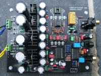
Would like confirmation on the pin 20 mod to the CS8416 chip; since there seems to be many different models of this DAC in this discussion.
The photo is of one of the model boards that does not use an adapter for the CS8416 chip, and is soldered directly to the board.
So regarding the pin 20 mod in this case; would it only require connecting a 47k resistor to a 3.3v or 5v digital supply direct to pin 20 of the CS8416.
Or do I need to lift pin 20 off the board then connect it to the resistor.
Thanks all.
Attachments
Working URL for Lawrence DAC
Sorry for the nonworking tinyurl.
Here's what I got.
http://cgi.ebay.com/UPGRADED-24bit-...h=item330314378576&_trksid=p4634.c0.m14.l1262
Sorry for the nonworking tinyurl.
Here's what I got.
http://cgi.ebay.com/UPGRADED-24bit-...h=item330314378576&_trksid=p4634.c0.m14.l1262
what can i say - very ugly soldering on that last picture,it would be a pain in the a** to desolder components and make all these modifications ...all they had to do is to use a better quality solder, but i assume that everything counts in these guys final production price to be able to make a bigger profit 
Re: Working URL for Lawrence DAC
Same thing with this one. You have to lift the CS8416 pin 20 on the chip and connect it with a 47k to 3.3V
Also, make this PLL components upgrade because these dacs have old values.
http://www.cirrus.com/en/pubs/errata/ER578D1.pdf
Mush said:Sorry for the nonworking tinyurl.
Here's what I got.
http://cgi.ebay.com/UPGRADED-24bit-...h=item330314378576&_trksid=p4634.c0.m14.l1262
Same thing with this one. You have to lift the CS8416 pin 20 on the chip and connect it with a 47k to 3.3V
Also, make this PLL components upgrade because these dacs have old values.
http://www.cirrus.com/en/pubs/errata/ER578D1.pdf
luxury54 said:what can i say - very ugly soldering on that last picture,it would be a pain in the a** to desolder components and make all these modifications ...all they had to do is to use a better quality solder, but i assume that everything counts in these guys final production price to be able to make a bigger profit
Do they really use low quality solder or this is the result of using ROHS lead free solder ?
Re: Working URL for Lawrence DAC
Yes, that looks very nice for < AU$200 (!!!)
Short signal path, basic power supply regulation, input isolation transformer, simple but effective analog filter and nice components - in particular analog filter resistors and caps (and fast switching soft recovery diodes for as rectifiers). It should be okay for the money.
Regards,
Boky
Mush said:Sorry for the nonworking tinyurl.
Here's what I got.
http://cgi.ebay.com/UPGRADED-24bit-...h=item330314378576&_trksid=p4634.c0.m14.l1262
Yes, that looks very nice for < AU$200 (!!!)
Short signal path, basic power supply regulation, input isolation transformer, simple but effective analog filter and nice components - in particular analog filter resistors and caps (and fast switching soft recovery diodes for as rectifiers). It should be okay for the money.
Regards,
Boky
Lawrence DAC
My problem is how tight everything is and also that the board silk screen labels are under the components. At a cursory glance I can guess at the PLL parts. It's so tight that I don't want to bother. I'd lift pin 20 of the 8416 but it's so small that I don't want to mess things up. The ugliest part of the board is the tightness and then the solder. The blue LEDs are hideously cute too. That said, I am still stunned at how good it sounds. I plan on doing some modding. I'll have to figure what the PLL cluster of parts are.
My problem is how tight everything is and also that the board silk screen labels are under the components. At a cursory glance I can guess at the PLL parts. It's so tight that I don't want to bother. I'd lift pin 20 of the 8416 but it's so small that I don't want to mess things up. The ugliest part of the board is the tightness and then the solder. The blue LEDs are hideously cute too. That said, I am still stunned at how good it sounds. I plan on doing some modding. I'll have to figure what the PLL cluster of parts are.
I modified extensively about 10 of these dacs.
I use a Hakko soldering station settled at 800 degrees. The traces on the boards never stripped or peeled.
Yes, many parts are tight fitted. As I am supposed to wear glasses and don't, I use a lamp with integrated magnifying glass to solder small parts.
I use a Hakko soldering station settled at 800 degrees. The traces on the boards never stripped or peeled.
Yes, many parts are tight fitted. As I am supposed to wear glasses and don't, I use a lamp with integrated magnifying glass to solder small parts.
Well, my second DAC arrived today and there are a few changes on the board as suspected. There is an area on the board (not populated) for a PCM2902 USB interface. The transformer for the coax digital input is gone and the area around the CS8416 is dfferent. The signals between the 8416 and DAC have been brought out to wire links so they can potentially be disconnected and perhaps looped through a reclocking chip although none is included on the board. There is an input select jumper on the 8416' piggy back board now.
On the analogue side the coupling electrolytics between the DAC and the filter stage are gone and the filter component layout has changed a little but the values still look the same so the filter is still likely to need work.
I will try and take some pictures later.
Kevin
On the analogue side the coupling electrolytics between the DAC and the filter stage are gone and the filter component layout has changed a little but the values still look the same so the filter is still likely to need work.
I will try and take some pictures later.
Kevin
I have also ordered this DAC - the "upgraded" version.... It arrived in less than a week. First impression is very good (for < AU$200)... it needs a lot of attention to become really good. It will go in a box and then to a friend of mine who's place was robbed..
Anyway, the first listening impression in its original form tels me that it's an absolute bargain...
Kudos to Lawrence who shipped the unit straight away - I received it in less than a week. He also responded to my e-mails promptly and provided (generic) circuit diagram in pdf.
Extreme_Boky
Anyway, the first listening impression in its original form tels me that it's an absolute bargain...
Kudos to Lawrence who shipped the unit straight away - I received it in less than a week. He also responded to my e-mails promptly and provided (generic) circuit diagram in pdf.
Extreme_Boky
Hello
I ordered a obviously similar kit from the eBay seller gigawork shop.
And I got this version:
Sounding quite good up to now.
But it has no input tranny for spdif an in the upper right corner there seems to be a connection for a switch to externally select the input source.
But this is not documented.
And also the jumpers in the same corner. The silkprint shows how to set the jumpers.
I will ask the seller. A layout of the print would be nice to have.
This version also seems to have electrolytics in the signal path. I think, I will replace the audio circuit by a tube circuit.
Franz
P.S.
I want to use it as an USB/SPDIF input for my Studer 52 amplifier, my actual project, built in a Studer OnAir500 mixer chassis:
I ordered a obviously similar kit from the eBay seller gigawork shop.
And I got this version:
An externally hosted image should be here but it was not working when we last tested it.
Sounding quite good up to now.
But it has no input tranny for spdif an in the upper right corner there seems to be a connection for a switch to externally select the input source.
But this is not documented.
And also the jumpers in the same corner. The silkprint shows how to set the jumpers.
I will ask the seller. A layout of the print would be nice to have.
This version also seems to have electrolytics in the signal path. I think, I will replace the audio circuit by a tube circuit.
Franz
P.S.
I want to use it as an USB/SPDIF input for my Studer 52 amplifier, my actual project, built in a Studer OnAir500 mixer chassis:
An externally hosted image should be here but it was not working when we last tested it.
An externally hosted image should be here but it was not working when we last tested it.
An externally hosted image should be here but it was not working when we last tested it.
Hi Franz,
your DAC is the same as offered by Lawrence Chan. If you stick with the op amps, the mod's to the low pass filter is the same as described in this thread.
Have you tested the USB port? Is it working Ok and did your PC/OS found it without any problems?
Nice amplifier!
your DAC is the same as offered by Lawrence Chan. If you stick with the op amps, the mod's to the low pass filter is the same as described in this thread.
Have you tested the USB port? Is it working Ok and did your PC/OS found it without any problems?
Nice amplifier!
it's not a problem that you don't have spdif transformer on board,one situated at the transport side it is enough .
I see that the vertical upsampler board is missing (i think you can order it separatelly and place it instead of those 5 jumpers)
but i see on board some nice silver mica caps (6 of them - 2 near spdif,4 near opamps),also some handy feritte beads near the dac for power supply noise rejection...i also see variable adjusting for opamp power supply,so i think it can be adjusted to 15V instead of 12V giving more headroom
Although i don't reccomend to use it on USB input because the PC's ground it's not galvanically isolated through this connection bringing you to the dac all the HF junk (and anyway USB protocol is far far away from being a quality "audiophille" music source - better hang with optical output which is galvanically isolating
the PC from the external DAC thus not affecting it's performance)
Beside all these,a lot of modifications are waiting for you on the board if you want to make it sound pretty good compared to existing (expensive) Hi-Fi CD-Player implementations
- Home
- Source & Line
- Digital Line Level
- Experience with this DIY DAC ?