erm I seem to get conflicting information now?
So it can or cannot be used? McGyver can you add a resistor to increase the resistance of the primary?
Now hold on, all 500 or 600ohm trafos look like a dead short. That is one reason you use Rs in series with each primary. Try 500ohms per leg.
Have a read here for some info on using this trafo http://www.prodigy-pro.com/diy/index.php?topic=22602.0 - LF problems !
Have a read here for some info on using this trafo http://www.prodigy-pro.com/diy/index.php?topic=22602.0 - LF problems !
That is a tube circuit with much higher output impedance, the DAC chip is around 100ohms. Those trafos are perfect. If you buy them and cant get them to work just send them to me and I will dispose of them for you.

Bill,
Shoog tried these trafos for a DAC output & gave up http://www.diyaudio.com/forums/showthread.php?p=1821809
http://www.diyaudio.com/forums/showthread.php?p=1819203
If you think they are good for a Vout DAC, I will try them (as I have 2 from Shoog) on my PCM1793 which wants a min gain impedance of 1.7K ohm - and report back. What value R should I use across the primary?
Apologies, if I have misled anybody but I read about the neg impedance requirement of this trafo & how it was not suited to DAC output stage somewhere (- I'll find the exact reference). However, I'm willing to do some tests & report my results!
Last edited:
Bill,
Shoog tried these trafos for a DAC output & gave up http://www.diyaudio.com/forums/showthread.php?p=1821809
http://www.diyaudio.com/forums/showthread.php?p=1819203
If you think they are good for a Vout DAC, I will try them (as I have 2 from Shoog) on my PCM1793 which wants a min gain impedance of 1.7K ohm - and report back. What value R should I use across the primary?
Apologies, if I have misled anybody but I read about the neg impedance requirement of this trafo & how it was not suited to DAC output stage somewhere (- I'll find the exact reference). However, I'm willing to do some tests & report my results!
Hey John, make sure there is no DC across the +/- outputs, I dont think there should be but it doesnt hurt to check.
1k in series on each leg should be good for starters. You only have about 1VRMS so you actually could wire it up 1-2 for more output.
Hey John, make sure there is no DC across the +/- outputs, I dont think there should be but it doesnt hurt to check.
1k in series on each leg should be good for starters. You only have about 1VRMS so you actually could wire it up 1-2 for more output.
Ok, Bill,
Can I ask some Qs:
- in other threads (and on my current trafo) I use a 2k R across the primaries - is this the same as a 1k in series on each leg of the primary?
Output form PCM1793 at bipolar zero is 1.4V, so I'll try 1:1 first to compare it to my existing 1:1 trafo - does this change the series R I should use?. Later I will try 1:2
Bill, you are correct, as usual - the Lundahl LL1517 work great - I'll try a few different configurations with it to see which sounds the best. I started with a 2.2K R across the primary but it sounds just as good without. So good news Havoc08, you can go buy those trafos
Should I try 1K in each primary leg?
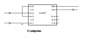
I have it wired up as 1:2 as in diagram - it sounds as good as the Slagle trafo, I think
I'm going to try 1:1
Should I try 1K in each primary leg?
I have it wired up as 1:2 as in diagram - it sounds as good as the Slagle trafo, I think
I'm going to try 1:1
Attachments
Last edited:
Bill, you are correct, as usual - the Lundahl LL1517 work great - I'll try a few different configurations with it to see which sounds the best. I started with a 2.2K R across the primary but it sounds just as good without. So good news Havoc08, you can go buy those trafos
Should I try 1K in each primary leg?
I have it wired up as 1:2 as in diagram - it sounds as good as the Slagle trafo, I think
I'm going to try 1:1
I would put some resistance in series with the primaries, 500 to 1K, To prevent overloading the chip. I couldn't find any dc load rating on the data sheet as some other chip's data sheets list.
Is 2K across the primary equivalent to 1K in series on each leg?
No, that is totally different. According to Bud, and he knows, the primary wants to see the source somewhat higher than the 100 or so ohms of the dac chip, so adding the series Rs helps both the chip and the trafos. If I was a trafo expert I could come up with a good number, but I'm not, and will never pretend to be. The correct value should give you a very slight rolloff at 20hz from what I have read. Your scope would be good for finding that, and it is probably slightly dependant on your downstream input impedance also, but that might be splitting hairs.
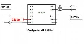
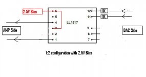
I also wanted to try to bias the transformer on the secondary side to 2.5V on the CT so I can avoid a DC blocking capacitor on the input of the Tripath amplifier which would have 2.5 V on each input lead if not for a blocking cap.
If I want to also try 1:2 configuration of the Transformer I need to turn it around and use the secondary connected to my DAC & the primary feeding the amp because it has 2 windings each with a center tap & I will be using one only with it's CT connected to bias.
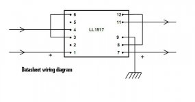
Diagrams attached
Edit: Thanks Bill, cross posting happened. I have my Slagle trafo wired with 2K across the primary (I picked up this notion from somewhere?) & it sounds wonderful. There may well be a bit more HF on the Slagle trafo - this would be the Nickle core & bifilar winding of the Slagle, I presume & not the 2K Racross the Pri? I should take this out now & put a 1K in series on each primary leg as per the LL1517s
If I want to also try 1:2 configuration of the Transformer I need to turn it around and use the secondary connected to my DAC & the primary feeding the amp because it has 2 windings each with a center tap & I will be using one only with it's CT connected to bias.
Diagrams attached
Edit: Thanks Bill, cross posting happened. I have my Slagle trafo wired with 2K across the primary (I picked up this notion from somewhere?) & it sounds wonderful. There may well be a bit more HF on the Slagle trafo - this would be the Nickle core & bifilar winding of the Slagle, I presume & not the 2K Racross the Pri? I should take this out now & put a 1K in series on each primary leg as per the LL1517s
Attachments

Last edited:
I found where I got the idea - it's on my other thread diagram & all & nobody corrected it? http://www.diyaudio.com/forums/showthread.php?p=1924584
Not doubting you, Bill, just double checking
Not doubting you, Bill, just double checking
Attachments
I also wanted to try to bias the transformer on the secondary side to 2.5V on the CT so I can avoid a DC blocking capacitor on the input of the Tripath amplifier which would have 2.5 V on each input lead if not for a blocking cap.
If I want to also try 1:2 configuration of the Transformer I need to turn it around and use the secondary connected to my DAC & the primary feeding the amp because it has 2 windings each with a center tap & I will be using one only with it's CT connected to bias.
Diagrams attached
Edit: Thanks Bill, cross posting happened. I have my Slagle trafo wired with 2K across the primary (I picked up this notion from somewhere?) & it sounds wonderful. There may well be a bit more HF on the Slagle trafo - this would be the Nickle core & bifilar winding of the Slagle, I presume & not the 2K Racross the Pri? I should take this out now & put a 1K in series on each primary leg as per the LL1517s
No need to turn the trafo around, but you could. Why don't you tie 8 and 12 together and apply the bias to that, and either use one primary winding or parallel the primaries.
If you are going to ground one leg of the trafo at the amp you will have to do it through a big cap or you will pull the bias to ground. I don't know enough about the Tripaths to help much there.
Last edited:
Havoc08,
Firstly, I'm no whizz, just a noobie to trafos too.
I'm still auditioning the LL1517 but initial impressions are that it's not as airy as the bifilar-wond on Nickel core Slagle transformer. I don't know if the LL1517s have any hours on them so I'm running them in for a while - I don't know if this will change. To be honest, I wouldn't notice the lack of HF extension (I presume that's what it is) if I didn't have the other trafos. Can't say I notice any difference in the LF response but I don't have any bass monster speakers. I won't have the Sescom trafos for a while to compare them also.
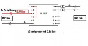
My Tripath amp is the Lepai, based on the TA2020. I think a lot of these Tripaths have a bias voltage on the input pins & have a biascap pin - pin 14 for the TA2020. This pin is connected to ground through a cap, I intend to remove the smd cap & connect the bias lead to it. Here's my schematic of how I will connect the trafo with the Tripath chip
Edit: Please check that I'm doing this correctly i.e. the 1:2 & also the bias connection!
Firstly, I'm no whizz, just a noobie to trafos too.
I'm still auditioning the LL1517 but initial impressions are that it's not as airy as the bifilar-wond on Nickel core Slagle transformer. I don't know if the LL1517s have any hours on them so I'm running them in for a while - I don't know if this will change. To be honest, I wouldn't notice the lack of HF extension (I presume that's what it is) if I didn't have the other trafos. Can't say I notice any difference in the LF response but I don't have any bass monster speakers. I won't have the Sescom trafos for a while to compare them also.
My Tripath amp is the Lepai, based on the TA2020. I think a lot of these Tripaths have a bias voltage on the input pins & have a biascap pin - pin 14 for the TA2020. This pin is connected to ground through a cap, I intend to remove the smd cap & connect the bias lead to it. Here's my schematic of how I will connect the trafo with the Tripath chip
Edit: Please check that I'm doing this correctly i.e. the 1:2 & also the bias connection!
Attachments
Last edited:
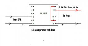
Maybe this is a better configuration that doesn't reverse Primary & secondary use. So primary goes to DAC & secondary goes to AMP
Havoc08, hope this helps?
Havoc08, hope this helps?
Attachments

Last edited:
Maybe this is a better configuration that doesn't reverse Primary & secondary use. So primary goes to DAC & secondary goes to AMP
Havoc08, hope this helps?
Don't forget to try them 1/1, it could make a big difference.
Whiz, that's not me, maybe cheese whiz.

Please excuse if this is a stupid question. I've got the UTA a-20's all set to connect to the DAC output and the caps have been removed. But for each output (R+,R-,L+,L-), there are 2 holes/pads. Yet I see everyone connecting w/ only 4 wires.
Which pad do I solder to? the shaded/striped pad? Or is there a step I'm missing?
Which pad do I solder to? the shaded/striped pad? Or is there a step I'm missing?
- Home
- Source & Line
- Digital Line Level
- Experience with this DIY DAC ?