JUST when you think you've got the best you can get (for the money spent) something else ALWAYS comes along hahaha! In this instance ignorance is bliss, and I am going to force myself to continue getting the best from this DAC.
Brianco, have you tried any other resistor values? What have you got on the primaries?
It does sound VERY open without any load - if the treble would smooth out a little and the bass open up again I'd be extremely happy with it. Seldom heard a DAC as open as this one.
Actually John, the Jensen circuit isn't a direct load, it's a filter. It might be just right for you, and don't be afraid to try different cap values.
Actually John, the Jensen circuit isn't a direct load, it's a filter. It might be just right for you, and don't be afraid to try different cap values.
I forgot to mention that I have a Russian teflon cap in series with the 1KR Tantalum across the secondaries. Also I have a similar cap across the primaries and 300R in series from the chip to transformer. It is in essence the Jensen filter.
Whilst replacing the components on the secondaries I remembered that the 300R resistors I used were prototypes of the Be Yam resistors made by Sfernice for Be Yamamura (Percy Audio still has some!) Although made in 10 or 12 values for a trial rum they were all marked as being 300R!!!!!! I checked them and found that one was in fact 1K6. I changed that to match the other 3 and the soundstage was about half way between what it had been and as when without any secondary components.
CD is not my first choice of source material as I have most of my music on good old 33s - some 4000 of them. My Technics SP 10 TT is suffering from Power Supply problems. [It is full of ICs long since redundant and needs more than an Avo & a DMM to diagnose the problem]. I am putting an old Lenco dd tt into a new plinth this week so will have a reference against which to judge the DAC. All I can say is that it is a long way better and more communicative of music than any I have played with in the past at the $1800-$2000 level of five years ago.
Anyone else with pops using the upsampling baord with the current V8 PCB?
Me. I'm going to try resoldering my connections, and maybe some of theirs as well tomorrow. I get pops with and without the upsampler, but there are definitely more with.
Sigh. I fixed the popping. It turns out that if you put the receiver board in backwards, the dac won't pop any more. Of course, it won't do much of anything else either. 
Anyone know if the smd boards that come with this dac are standard ssop28 to dip boards, or do they have a custom pinout?
I'm trying to decide whether to order a chip, a new dac board entirely, or scrap this and try out some of the other dacs out there. I'm not sure that my problems weren't from something on the board, rather than just damaged chips, before i finished them off. I'm reluctant to try again with the same seller for more money. This dac just keeps going up in price.
Hmm. maybe I can see if he'll sell me only the smd boards.
Oh well.
The SMD boards use surface mounted chips with + and - outputs going through capacitors before an incorrectly setup single opamp output stage.
The post reg caps on my big board look either dirty or old, and have less bright print than genuine examples of those Elna RJH caps that I happen to have. I'm wondering if the caps are bad or chips are bad, or whether they just have little quality control. They aren't getting any more of my money whilst problems are common.
The post reg caps on my big board look either dirty or old, and have less bright print than genuine examples of those Elna RJH caps that I happen to have. I'm wondering if the caps are bad or chips are bad, or whether they just have little quality control. They aren't getting any more of my money whilst problems are common.
johnm said:I'm just a bit concerned with desoldering the components. I have a 50w Weller soldering iron with a small-ish tip, and a 25w Weller with a pencil tip. I'm guessing I'll have to use the 50w because of those large psu/earth traces and wriggle the leads out carefully. Last time I tried this I lifted the through-plated hole so can't say it's something I'm looking forward too
Hi johnm,
1/4 watt resistors should work in the signal path; there is much debate on the sound of resistors as well...
As for the desoldering process on this board, take the advice of the other guy who said that changing parts on this DAC board takes time and effort.
You will need a pretty hot iron with a small chisel tip which will heat the lead holes very fast; use a thin braid solder wick to help take some of the solder away.
Be careful not to try and pull the parts out unless the pad is hot enough to keep the solder melted, otherwise it is pretty easy to lift the trace lead pads.
You may need to clear the holes as the other guy explains.
Good luck with your mods.
Crap, I learned this the hard way. I partially removed the solder pads for the R- cap while desoldering

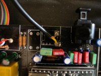
COAX input
My coax and optical inputs don't work (USB does). I use a RCA plug on the chassis to connect to the coax input. The picture shows how this is connected.
Does anyone know if i have to connect the wire (yellow) also to the solder pad next to the one it is connected to?
My coax and optical inputs don't work (USB does). I use a RCA plug on the chassis to connect to the coax input. The picture shows how this is connected.
Does anyone know if i have to connect the wire (yellow) also to the solder pad next to the one it is connected to?
Attachments
Actually John, the Jensen circuit isn't a direct load, it's a filter. It might be just right for you, and don't be afraid to try different cap values.
I may have been hasty to point the finger of blame at the lack of any secondary load. Installed another pre-amp and the sound is far more balanced now (my suspicions were aroused when my vinyl sounded too bright as well - this is all after installing Elna Cerafine caps in the output of my Quad 34... but that's off topic here). Incredibly open sound and the detail is insane... but not forced out at you, if that makes sense! There is still the odd crescendo that makes me wince but it may well be worth it for this sense of openness. Still I'll give the secondary filter a try just to make sure.
- J
I soldered to the adapter pins on top and you are correct, they do correspond with the chip legs, I just refered to the DACs data sheet and tested with a multi.The output must be on one of the the legs of the DIN adapter, I suppose that each adapter pin directly corresponds to the chip leg, clearly it would be prudent to check this before soldering.
Those tiny holes are a nightmare Chinese.
Though he may want to do the solder joins quick as he would not want to heat the chip too much.
Could the Lundahl LL-1517 be used as audio transformer for this application? I can't seem to find hoe many ohms the prim. and sec. are, but maybe some of you enlightened people know? http://www.lundahl.se/pdfs/datash/1517.pdf
Could the Lundahl LL-1517 be used as audio transformer for this application? I can't seem to find hoe many ohms the prim. and sec. are, but maybe some of you enlightened people know? http://www.lundahl.se/pdfs/datash/1517.pdf
I think this trafo wants to be driven with a negative impedance of -18ohm AFAIR, so the answer is likely to be no, it can't be used!
thx jkeny and damn.. I could get these really cheap around £50-£70 a pair.
I might just have to try the edcors then as I'm on a budget
I picked up some Sescom MI-97 (NOS & working) on ebay for $50 the pair (I avoided the $83 shipping to Europe by getting a friendly US citizen to act as forwarder) - so that might be a possibility!
Could the Lundahl LL-1517 be used as audio transformer for this application? I can't seem to find hoe many ohms the prim. and sec. are, but maybe some of you enlightened people know? http://www.lundahl.se/pdfs/datash/1517.pdf
Should work great. You cant lose.
- Home
- Source & Line
- Digital Line Level
- Experience with this DIY DAC ?