I know this thread focus at output trannies at this moment but I still would like to share my impressions of four different opamps in the output stage.
This is my impressions graded from best to worst.
1. opa2107 revealing details and distinct impact in the lower regions. Great imaging and voices sounds natural and smooth. This is the overall winner of the four.
2. lm4562 overall good performance but a bit "shouty" in midrange and not that airy and detailed as the opa 2107 in the heights. Nice lower bass and midbass.
Sounds nice or perhaps as good or slightly better than the opa2107 in plain acoustical music.
3. NE5532. This is the opamp that the dac are delivered with. It sounds quite ok but there is some lack of details in the heights and a quite boring sound in the mid-range. Can't put my finger on it but there is a bit fatigue feeling when listening to it.
4. opa2134 Very disappointed to this opamp. I've heard quite good about this one but one thing is for sure: this is not my personal flavor. It sounds dark, dull and bass is indistinct and sloppy.
Have anyone tried the AD8066? That would probably be my next try.
Regards H@kan
Just ordered the Cinemag CMOB-2H's so hopefully l dom't have to wait weeks for them ")
McCrackers , it'll be interesting to see how your transformers compare .
Data, yeah l could'nt find much at all re the 10k stuff , just the lead info ,
are your Cinemags shielded , and if not would it be worthwhile isolating/shielding them?
Those tumura's are supposed to be nice too hey
cheers ken
McCrackers , it'll be interesting to see how your transformers compare .
Data, yeah l could'nt find much at all re the 10k stuff , just the lead info ,
are your Cinemags shielded , and if not would it be worthwhile isolating/shielding them?
Those tumura's are supposed to be nice too hey
cheers ken
Earlier this week I placed an order for the CMOB-2H. I pored over the CMOB/CMOQ data sheets and the only real difference I could see was the phase angle graphs looked a lot better on the CMOB. I'm also skeptical of any audible difference of phase, but since the CMOB was slightly cheaper too I went that direction. When I've received them and hooked them up I'll report back.
Looking forward to see what you think of them ...hopefully you don't have to wait too long
cheers ken
hi franz,
then i got you wrong, sorry!
chris
edit:
pic of my finished dac:
ill only change the digital input to spdif...
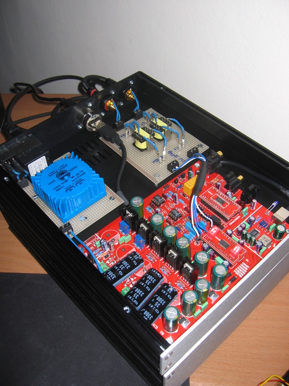
xTr3Me , what case is that you have used ? looks nice
cheers ken
Help Please! I'm hoping someone can sanity check my plans for wiring up my IEC connector, R-core (R26-34) and DAC as I'm pretty sure I've got it wrong. I haven't been able to find a good guide for the r-core (plenty for default toroids).
The advice I was provided from diyclub regarding the r-core:
I don't really understand the part about connecting the two 0-15V in series then wiring 15 0-15 0 (or does this mean the 0-15 is actually a blue and grey connected together into the 0V?)
Current Layout
IEC
E - earth?
L - live?
N - neutral?
R-core
PRIMARY
Red (dot)
->115V
Yellow
Green (dot)
->115V
Orange
SECONDARY
2 x Brown (9V)
2 x Black (9V)
2 x Grey (15V)
2 x Blue (15V)
EARTH
1 x Yellow/Green
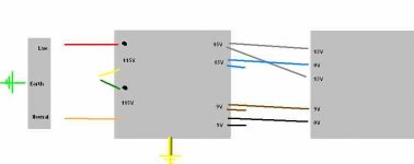
Proposed setup
PRIMARY
* Chassis earth -> IEC Earth
* 1 x Red (dot) -> IEC Live
* 1 x Yellow -> 1 x Green (dot) (to obtain series 230V for Australia)
* 1 x Orange -> IEC Neutral
SECONDARY
* 1 x Grey -> DAC 13V
* 1 x Blue -> DAC 0V
* 1 x Grey -> DAC 13V
* 1 x Brown -> DAC 9V
* 1 x Black -> DAC 0V
EARTH
* R-core yellow/green earth -> Chassis ground
I'm not sure about the 0V connections to the DAC - another poster from stereo.net suggested these needed to be connected to ground
Thanks,
Michael.
The advice I was provided from diyclub regarding the r-core:
the R26-4 have two group of 0-15v and two group of 0-9V wiring, just connect the two 0-15V in series then you wiring is look like 15 0-15 0, then connect one of the 15V wiring to you DAC 13V, the 0-15 wiring to 0, and then the remain wiring to other 13V,
and about the 9V just you one of the 0-9V
I don't really understand the part about connecting the two 0-15V in series then wiring 15 0-15 0 (or does this mean the 0-15 is actually a blue and grey connected together into the 0V?)
Current Layout
IEC
E - earth?
L - live?
N - neutral?
R-core
PRIMARY
Red (dot)
->115V
Yellow
Green (dot)
->115V
Orange
SECONDARY
2 x Brown (9V)
2 x Black (9V)
2 x Grey (15V)
2 x Blue (15V)
EARTH
1 x Yellow/Green
Proposed setup
PRIMARY
* Chassis earth -> IEC Earth
* 1 x Red (dot) -> IEC Live
* 1 x Yellow -> 1 x Green (dot) (to obtain series 230V for Australia)
* 1 x Orange -> IEC Neutral
SECONDARY
* 1 x Grey -> DAC 13V
* 1 x Blue -> DAC 0V
* 1 x Grey -> DAC 13V
* 1 x Brown -> DAC 9V
* 1 x Black -> DAC 0V
EARTH
* R-core yellow/green earth -> Chassis ground
I'm not sure about the 0V connections to the DAC - another poster from stereo.net suggested these needed to be connected to ground
Thanks,
Michael.
Attachments
That was me, but in that description it looks like you have no '0' taps coming from that transformer.
R-core
SECONDARY
2 x Brown (9V)
2 x Black (9V)
2 x Grey (15V)
2 x Blue (15V)
See by what you posted it looks like you only have active secondaries (with voltage), and no '0' taps
I'm very confused?
R-core
SECONDARY
2 x Brown (9V)
2 x Black (9V)
2 x Grey (15V)
2 x Blue (15V)
See by what you posted it looks like you only have active secondaries (with voltage), and no '0' taps
I'm very confused?
Yes!does this mean the 0-15 is actually a blue and grey connected together into the 0V?)
But then you have to measure that the remaining blue and grey make 30 V AC on them. If not connect the other one of the blues to the grey one.
Then the two that make 30V you connect to the two 13V connections and the two you already put together you put on the 0V connection.
For the 9V you either take the two brown wires or the two black ones.
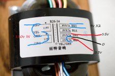
Hi rhinomite
I have the same transformer (R26-34) and asked Ian Ma advice. He now supplies an R-core transformer instead of the toroid (typical!)
His has different colour wires but he sent me this diagram to help.
In place of the blue - 9V use both blacks (browns not used so snip ends and tie safely in knot)
in place of the yellow - 15V use grey
in place of the brown - 15V use blue
Twist spare grey and blue ends together and connect to middle 0V
I'm in UK so for 240V primary use red for Live and orange for neutral
Then twist ends of yellow and green primary's together to make connection (solder together or crimp)
Connect earth wire (yellow/green striped) to IEC socket if using metal chassis.
Hope that helps
Rich
I have the same transformer (R26-34) and asked Ian Ma advice. He now supplies an R-core transformer instead of the toroid (typical!)
His has different colour wires but he sent me this diagram to help.
In place of the blue - 9V use both blacks (browns not used so snip ends and tie safely in knot)
in place of the yellow - 15V use grey
in place of the brown - 15V use blue
Twist spare grey and blue ends together and connect to middle 0V
I'm in UK so for 240V primary use red for Live and orange for neutral
Then twist ends of yellow and green primary's together to make connection (solder together or crimp)
Connect earth wire (yellow/green striped) to IEC socket if using metal chassis.
An externally hosted image should be here but it was not working when we last tested it.
Hope that helps
Rich
Last edited:
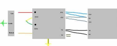
I set Ian Ma a pic of my R26-34 and he sent back the below pic.Help Please! I'm hoping someone can sanity check my plans for wiring up my IEC connector, R-core (R26-34) and DAC as I'm pretty sure I've got it wrong.
I don't really understand the part about connecting the two 0-15V in series then wiring 15 0-15 0 (or does this mean the 0-15 is actually a blue and grey connected together into the 0V?)
In a nutshell, yes you connect both a blue and a gray wire to the 0v.
Attachments
what would cause buzzing
Hi I finally got of my **** and put together the DAC using the UTC-20, I got it all working and just switched it on and after some small issues got it all working.
However there is a buzzing sound that can be heard when listening with any decent listening volume levels, anybody got any ideas.
I,m using I a 1k resister on each leg of primary and the secondary I,m using a 680 ohm, so I'm basically using the same setup as the Tamura Trans Connection without the ground.
you have no grounding connected?
I have ground for the power only, but I thought both the DAC and transformer are differential devices so grounds not needed ?.
- Home
- Source & Line
- Digital Line Level
- Experience with this DIY DAC ?