Re: Graphs
mine is slightly better, compare prices and you'll have your answer
QSerraTico_Tico said:I don't see much difference in the plots between the LCaudioXO3 and the 33.8688MHz Tent clock.
So?

mine is slightly better, compare prices and you'll have your answer
Re: Re: Graphs
Actually I only compare sound.
I found the LCaudio a little bit better than the Tent in sound so I think these graphs ar not conclusive.
Guido Tent said:
mine is slightly better, compare prices and you'll have your answer
Actually I only compare sound.
I found the LCaudio a little bit better than the Tent in sound so I think these graphs ar not conclusive.
Re: Re: Re: Graphs
what you prefer soundwise does not have to be the best performing clock in terms of jitter
it depends what you are after, transparancy or euphonics
QSerraTico_Tico said:
Actually I only compare sound.
I found the LCaudio a little bit better than the Tent in sound so I think these graphs ar not conclusive.
what you prefer soundwise does not have to be the best performing clock in terms of jitter
it depends what you are after, transparancy or euphonics
Re: Re: Re: Re: Graphs
I find transparency, or the lack of it, not a strong point of your clock. So I wonder why you bring that up.
Guido Tent said:
what you prefer soundwise does not have to be the best performing clock in terms of jitter
it depends what you are after, transparancy or euphonics
I find transparency, or the lack of it, not a strong point of your clock. So I wonder why you bring that up.
CraigBuckingham said:
Those recording engineers are misguided.
Rubidium master clocks are optimised for good long-term stability as time references. Very short-term stability or phase noise that is in the low end of the audio band is therefore not as critical a design parameter.
Current state of the art crystal oscillators are virtually at the limits that physics dictates for the type or resonator used. SC cuts performing better than AT cuts.
Rubidium master clocks use a CRYSTAL OSCILLATOR stabilised to the rubidium hyperfine transition of 6 834 682 610.904 324 Hz. It is that hyperfine transition frequency accuracy that gives long-term accuracy by the use of synchronising to it.
The short-term accuracy is determined by the CRYSTAL OSCILLATOR used in the rubidium standard.
A brief description on that can be found here http://en.wikipedia.org/wiki/Rubidium_standard
A more detailed description here http://www.thinksrs.com/products/PRS10.htm
So to put it in simple terms the Rubidium standard oscillator is superfluous, redundant - lowers performance and adds unnecessary cost when applied to high quality audio/digital conversion.
Spot on, and thanks for this post, also from my Grimmaudio colleagues
Terry Demol said:
Misguided? They are merely reporting and acting on what they
hear. When a number of engineers report similar findings then it is
worth investigating what mechanisms are actually occuring.
I'm not so much interested in the absolute performance of
Rubidium, more the ADC's behaviour when being externally clocked
by one.
I suggest you go to:
http://www.grimmaudio.com/whitepapers.htm
Read whitepaper titled 'PLL and Clocking'. In particular point 7.
As shown in the graph, the only region an externally clocked ADC
can benefit is below the internal PLL's cutoff point, ie; low
frequencies. (Good paper Grimmaudio folks)
Others are getting benefits from ULN at LF PSU's on their oscillators,
so the finger points at one region - close in (to carrier) phase noise.
Dig?
T

You said,
This seems to be the case, there are plenty of recording engineers
throwing good hard earned cash at Rubidium master clocks.
As a generalisation, this frequency area is the only real possibility for
improvement when slaving an ADC off an external clock.
cheers
Terry
Terry,
1) Yes, they are misguided. Firstly by some manufacturers of Rubidium master clocks aimed at that market.
2) By people such as yourself suggesting they offer better close in noise performance.
You made the association about close in noise being asscociated with Rubidium master clocks.
In my reply to your post I countered with substantial references to why that was not the case.
What you are or are not interested in does not change the laws of physics. You need to understand that the physical world is not influenced by human emotion.
If you did not understand my post I suggest re-read it.
What is important is to understand why your assertions are not correct because of how a Rubidium master clock works. Then you will understand why a good oscillator is a better approach than a Rubidium master clock.
Try using google and do some research on the history and performance of crystal oscillators and you may have a better understanding on the subject matter.
Talk to experts, such as those ar NIST or Wenzel, SRS etc.
You may be able to then add some more usefull information to the subject thread.
Re: Re: Re: Re: Re: Graphs
Ergo you can't just sit down and listen to a signal and declare that "transparent". You have to get hold of the same signal upstream in the signal chain and compare it A/B. Guido's clock was tested (against others) in this manner, by equipping AD and DA converters with a variety of clocks and comparing the AD input and the DA output. And yes: some clocks sounded like the DA output had much more going for it than the AD input, at least on some genres of music. But that is not what transparency is about.
It's fine if you prefer LC's clock. No problem. It just means you're into euphonics, not transparency. There is nothing wrong with euphonic, point is to know what you're after and then going after it directly.
Simple. Transparency means "not changing the sound in any way". There are many ways of improving the apparent amount of microdetail in reproduction (usually to the detriment of microdynamics or tonal neutrality). I've often encountered boxes that, when you add them to a signal chain, increase apparent immediacy and detail markedly. Here's the crunch: at that point the signal at the output of the box has a lot more detail and atmosphere than the input does. This obviously means the output sounds clearly different from the input and that the box is therefore NOT transparent.QSerraTico_Tico said:I find transparency, or the lack of it, not a strong point of your clock. So I wonder why you bring that up.
Ergo you can't just sit down and listen to a signal and declare that "transparent". You have to get hold of the same signal upstream in the signal chain and compare it A/B. Guido's clock was tested (against others) in this manner, by equipping AD and DA converters with a variety of clocks and comparing the AD input and the DA output. And yes: some clocks sounded like the DA output had much more going for it than the AD input, at least on some genres of music. But that is not what transparency is about.
It's fine if you prefer LC's clock. No problem. It just means you're into euphonics, not transparency. There is nothing wrong with euphonic, point is to know what you're after and then going after it directly.
Re: Redbook vs. Good Sound
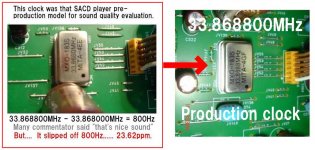
If the replay clock is a static 100ppm (0.01%) over the standard frequency, this corresponds to a 1.80m violinist playing a 50cm violin sounding like they are in fact 180um and 50um smaller, respectively. The 30m large concert hall in which he plays will sound 3mm smaller. Exceedingly plausible, I grant you.
Lars Clausen said:
However i think 100ppm deviation is in fact audible in an A/B test.
If the replay clock is a static 100ppm (0.01%) over the standard frequency, this corresponds to a 1.80m violinist playing a 50cm violin sounding like they are in fact 180um and 50um smaller, respectively. The 30m large concert hall in which he plays will sound 3mm smaller. Exceedingly plausible, I grant you.
Very amusing analogy Guido, even though i'm having a hard time figuring out how the height of the musician affects the pitch of the music. Anyway i'm sure you have a good explanation for that
How does jitter then fit into your classical musician formula? Rumbling in his stomache??
How does jitter then fit into your classical musician formula? Rumbling in his stomache??
Re: Redbook vs. Good Sound
We JAPANESE, -23.62ppm diviation can not in fact audible.
Lars Clausen said:
However i think 100ppm deviation is in fact audible in an A/B test.
??
We JAPANESE, -23.62ppm diviation can not in fact audible.
Attachments
Re: Re: Redbook vs. Good Sound
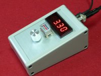
Few years ago, I have held clock unit audition party.
I made variable voltage clock power suplly, and hearing test.
We JAPANESE can audible -20ppm difference, if +3.3V clock unit's standard supply voltage change to +2.85V.
But in this difference, cause was increse phase noise, not clock speed fast.
nagaesan said:
We JAPANESE, -23.62ppm diviation can not in fact audible.
Few years ago, I have held clock unit audition party.
I made variable voltage clock power suplly, and hearing test.
We JAPANESE can audible -20ppm difference, if +3.3V clock unit's standard supply voltage change to +2.85V.
But in this difference, cause was increse phase noise, not clock speed fast.
Attachments
Re: Re: Re: Redbook vs. Good Sound
You raise a very important point. When performing such test, indeed, one should measure the jitter at all frequencies tested. Since most clock manufactureres are not able to measure the jitter of their clocks, I have good reason to doubt on the care of such tests.
Thank you for your contribution
nagaesan said:
Few years ago, I have held clock unit audition party.
I made variable voltage clock power suplly, and hearing test.
We JAPANESE can audible -20ppm difference, if +3.3V clock unit's standard supply voltage change to +2.85V.
But in this difference, cause was increse phase noise, not clock speed fast.
You raise a very important point. When performing such test, indeed, one should measure the jitter at all frequencies tested. Since most clock manufactureres are not able to measure the jitter of their clocks, I have good reason to doubt on the care of such tests.
Thank you for your contribution
LM329???
A string of green LEDs has an order of magnitude less noise. See Christer's noise measurement document on this forum.
See also:
http://www.diyhifi.org/forums/viewtopic.php?f=36&t=1721
I did some investigation into this claim last night. Always fun to play with noise design. Everyone should have a "Christer circuit", at least
It's true that a string of green LED's actually have lower RMS noise, than the LM329, but only at higher frequencies, like 1k and 10k. The LM329 is perfect flat white noise spectrum, while the LED's have low noise at high freq, but rising towards lower freqs.
The problem is, that if you have noise at 10k it's usually always filtered out by an RC network, and so you dont need your ref. to have low noise at high freq's. Most clock ciruits use like a resistor and a good OSCON cap for rail filtering.
So this leaves us with low frequency noise perfomance. and here the LM329 is somewhat better than the green LED's.
Lars Clausen said:
The LM329 is perfect flat white noise spectrum
it would be the first semiconductor based reference that does not suffer from 1/f noise
on page 6
http://www.national.com/ds/LM/LM329.pdf
National shows that they still have to deal with semiconductors physics
Lars, check your measurements, or tell us where you buy this special version of the LM329 !!!
LC, could you provide spectral plots? Some band-gap references are fairly "white" over the audio range simply because their broadband noise is so high that the 1/f noise doesn't stand a chance above a few Hz. LEDs OTOH (noise varies with type) have very low wideband noise and even though their 1/f noise is likewise quite low it still results in a higher corner. So if you could put both measurements in a single plot and calibrate this plot in nV/rtHz (so that it can be cross-checked with specs and measurements done by others) that would be most informative. Note that not all LEDs have the same noise performance.
Another question, of course, is how the clock oscillator responds to supply noise. Some circuits make brilliant VCO's, some others have a <1ppm deviation over a 50% supply change.
Another question, of course, is how the clock oscillator responds to supply noise. Some circuits make brilliant VCO's, some others have a <1ppm deviation over a 50% supply change.
OK Guido if you say so
My results are just based on reading of the spectrum analyser, looking at the noise of the actual semiconductor.
I thought that was the whole idea of Christer's practical noise analysis approach. ;-)
Guido, another thing, what kind of oscillator circuit is inside your metal cans? Inverter based Pierce?
Best regards
Lars Clausen
Bruno, thanks for your comments.
I will make the FFT plot's ready and post them here within a few days.
I think you are right in your assumptions about why the output reading of the LM329 is flat. However this way we can probably agree, that the frequency area to focus on, would be the lower freqencies, as the higher are filtered out anyway...
All the best from
Lars Clausen
Lars Clausen said:OK Guido if you say so
My results are just based on reading of the spectrum analyser, looking at the noise of the actual semiconductor.
I thought that was the whole idea of Christer's practical noise analysis approach. ;-)
Guido, another thing, what kind of oscillator circuit is inside your metal cans? Inverter based Pierce?
Best regards
Lars Clausen
Hi Lars,
Measuring noise is indeed fun, but not the easiest subject within electronics, I'd suggest to check your noise floor, as Bruno suggests.
Inverter based oscillators are not good enough
best
@LC, re flat vs 1/f:
By that reasoning a regulator could be improved by adding a white noise source. Allow me to provide a practical example: http://www.hypex.nl/docs/hxr.pdf (page 2) compares the noise spectra of a LED based regulator (lower curve) with standard regulators. The one labeled "B" (ON semi MC7812) is white down to <10Hz, so according to your reasoning it is better than the LED based one because the latter has a 1/f corner well inside the audio band. Of course, if anyone seriously believes this, they can always "improve" the circuit by adding 40nV/rtHz white noise, thus shifting the 1/f corner out of the audio band. I don't think anyone would seriously propose doing so.
The plot also provides a good ball-park figure of what a 12V LED string does noise-wise (the rest of the circuit has a negligible noise contribution). If your measurements differ by a large amount, you might consider using different LEDs or verifying the short-circuited input noise of the analyser.
- Status
- This old topic is closed. If you want to reopen this topic, contact a moderator using the "Report Post" button.
- Home
- Source & Line
- Digital Line Level
- 16.9344MHz LOW JITTER CLOCK KIT...