First off, thank you for your time reading this.
There are a few questions:
1.) What type of circuit do I need to make?
2.) Is there any other suggestions on how to go about this?
I am trying to figure out how to build a circuit that puts out a constant voltage with a sudden short "pulse" voltage/ground.
This is for a automotive 12volt application. When I press my remote lock/unlock button, there will be a very short ground connection. This ground connection is just enough to make the cars horn honk to tell you that the car is locked.
I am wanting to build something to where i can take this sudden short ground connection and make it into a longer connection(being either +12v signal or a ground signal). Would this be accomplished with a timer circuit? If so, what direction should i go to learn how to build one?
Again, thank you for your time!
This circuit should give you some ideas on how you might be able to convert a pulse into a control signal. No need to use reed relays like this one. The simple method would be a latching relay, but that's no fun ")
http://www.just4sheep.com/public/timer.pdf
http://www.just4sheep.com/public/timer.pdf
Will this circuit work to extend the pulse? I am definitely not a pro circuit builder so ill explain what im trying to do here:
Where the ground connection is, when the remote control module makes that brief ground connection to sound the car's horn, I want the capacitor there to charge up as much as possible(using the variable resistor to 'tune' the resistance that i need, or a fixed resistor, maybe 5 or 10 ohms, so it wont seem like a dead short) and to have the relay activate. When the ground connection is disconnected, the capacitor will discharge into the relay, keeping it open for a bit longer. if this pulse isn't long enough then i can add another stage of a bigger capacitor and a relay or transistor(since i can put a positive voltage from the first relay to the base of the transistor) to create a longer ground or positive voltage connection.
Also I'm not sure if the diode is needed or not in this circuit.
Again, this may seem like a crude setup but im still learning about the uses and how to piece together electrical components. Im just getting into transistors and their uses so i have a ways to go still.
Here is the schematic:
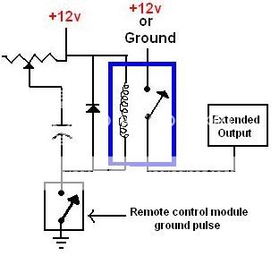
Again, thanks for your time!
Where the ground connection is, when the remote control module makes that brief ground connection to sound the car's horn, I want the capacitor there to charge up as much as possible(using the variable resistor to 'tune' the resistance that i need, or a fixed resistor, maybe 5 or 10 ohms, so it wont seem like a dead short) and to have the relay activate. When the ground connection is disconnected, the capacitor will discharge into the relay, keeping it open for a bit longer. if this pulse isn't long enough then i can add another stage of a bigger capacitor and a relay or transistor(since i can put a positive voltage from the first relay to the base of the transistor) to create a longer ground or positive voltage connection.
Also I'm not sure if the diode is needed or not in this circuit.
Again, this may seem like a crude setup but im still learning about the uses and how to piece together electrical components. Im just getting into transistors and their uses so i have a ways to go still.
Here is the schematic:
Again, thanks for your time!
It will work, but there are limitations:
Depending on the size of the R and C, the short pulse may not be enough to sufficiently charge up the capacitor, which will then fail to cause the relay to close. The smaller the capacitor, the faster it charges, and the better success you have getting the relay to close.
When the pulse is gone, the capacitor will hold the relay closed. The larger the capacitor, the longer the relay will remain closed for whatever you want to do. This is at odds with the first goal, which was to minimize the capacitor size.
Depending on your time constants, a design like this will inevitably result in an assortment of physically large devices. Easier to implement with your specific needs with 555 timers, especially since you have a permanent source of 12V available to use.
- Status
- This old topic is closed. If you want to reopen this topic, contact a moderator using the "Report Post" button.