Hi all. I hope this is the right section to post this question.
I recently purchased a North Star Model 192 MkI DAC from an official distributor in the US. Where I live we use 220V like Europe, so the distributor performed the voltage modification as per North Star instructions (simple rewiring of transformer and changing of fuse). He said he checked it with a 220V upconverter and it worked perfectly and quietly. I received it and it is fully operational. However, there is an audible hum/buzz/noise. I have tried different power cables, interconnects, AC receptacles etc. but the hum/noise remains. The hum/noise goes up in volume as the volume knob of the amp is turned up. Also, the noise/hum seems to be only in the left channel.
In order to troubleshoot I have tried the following: I disconnected the earth wire on the AC plug of the power cable. When I used this unearthed power cable, the noise completely disappears. When I reconnected the earth, the noise returns.
I thought this may indicate a ground loop issue? However I have read that ground loop noise does not usually increase in volume when an amp is turned up, so I am not sure if that is the cause. I also know that running the DAC without an earth is dangerous and I would not want to put either myself or the equipment in danger of course (safety is most important). I tried connecting a different source (an old CD player) and it is dead quiet with no noise/hum. When I check the power cable of that CD player, I can see that there is no earth connected.
Unlike that CD player though, the North Star DAC is designed to be earthed using a normal 3-wire power cable. On the back of the DAC though it states "this device should be earthed". (The CD player has a hard-wired cable with only the two wires)
I tried connecting just one RCA interconnect cable at a time. With the right cable only, there is no noise; with the left cable only, the noise comes back. When I swap the cables around, the noise moves to the right side. To try eliminate it being an issue with the amp I tried the following configurations (with two different sets of interconnect cables to make sure it wasn't a problem with the cables):
- both channels connected, hum/noise in left channel
- right channel connected only (to right input of amp), no hum/noise
- left channel connected only (to left input of amp), hum/noise in left channel
- left channel connected only (to right input of amp), hum/noise in right channel
- right channel connected only (to left input of amp), no hum/noise
Does this possibly indicate an issue with the grounding of the left RCA jack of the DAC? Or, could it be that the ground is only connected via the left channel RCA interconnect? Does the above "exonerate" the amp as being the culprit? This is stricly a headphone system, using the Woo Audio WA2 headphone amp / preamp.
Also one thing to mention - I was trying out another DAC about a month ago and it had the same type of issue: noise/hum in the left channel, increased with volume increase on amp. I did not try that without an unearthed power cable though as I thought it was a problematic DAC.
Can anyone assist in troubleshooting what the problem could be, and how it can be permanently and safely resolved?
Cheers
X
With both channels connect but swapped the hum is in the right.
Last night was very confusing - to confirm 100% that lifting ground/earth eliminated the hum, I disconnected the earth wire again on the power cable and hooked everything up. Noise/hum was back! Tried a regular power cable again (earthed) - same hum/noise. Connected the old CD player - silent background and clean.
Last night was very confusing - to confirm 100% that lifting ground/earth eliminated the hum, I disconnected the earth wire again on the power cable and hooked everything up. Noise/hum was back! Tried a regular power cable again (earthed) - same hum/noise. Connected the old CD player - silent background and clean.
xenithon said:With both channels connect but swapped the hum is in the right.
That rules out the amp as the cause. It still may be that the DAC in another system works fine. I had a similar unhappy marriage between a Micromega DAC1 and my DIY headphone amp.
Did you try the DAC on another amp?
Last night was very confusing - to confirm 100% that lifting ground/earth eliminated the hum, I disconnected the earth wire again on the power cable and hooked everything up. Noise/hum was back! Tried a regular power cable again (earthed) - same hum/noise. Connected the old CD player - silent background and clean.
That rules out the earthing as the cause. If the DAC's L channel also hums in another system, the fault lies there. Trying the DAC in another system would be my next step.
In the meantime one thing you could try is turn the toroidal transformers in the DAC a little, see if that has any influence.
BTW, can you plug the power supply in SA two ways like in the part of mainland Europe that use Schuko plugs and sockets? Sometimes turning a plug 180 degrees (swapping L and N) can be a cure for hum.
I took the DAC to a hi-fi technician today. We opened it up and checked it using a voltmeter and oscilliscope (not that easy as we do not have a schematic).
We found the following:
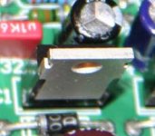
- in one area of the power supply section, on the PCB, there are three components (look like the component in the attached image; I am not sure what they exactly are ) in a row.
- one of these (labeled IC1) measures roughly 3.3V and is flat on the 'scope
- the second one (labeled IC2) measures roughly 5V and shows a 0.2V point-to-point ripple on the 'scope
- the third one (labeled IC3) measures roughly 9V and shows a large 1.4V point-to-point ripple on the 'scope
He also measured the outputs on the scope. The left RCA jack exhibits a 0.4V ripple (right output is flat/silent, as it should be).
As to what the above actually means and how it can be fixed, I do not know. I have sent the info to the manufacturer and am awaiting a reply. I don't suppose you could shed some light on this?
We found the following:
- in one area of the power supply section, on the PCB, there are three components (look like the component in the attached image; I am not sure what they exactly are
) in a row.- one of these (labeled IC1) measures roughly 3.3V and is flat on the 'scope
- the second one (labeled IC2) measures roughly 5V and shows a 0.2V point-to-point ripple on the 'scope
- the third one (labeled IC3) measures roughly 9V and shows a large 1.4V point-to-point ripple on the 'scope
He also measured the outputs on the scope. The left RCA jack exhibits a 0.4V ripple (right output is flat/silent, as it should be).
As to what the above actually means and how it can be fixed, I do not know. I have sent the info to the manufacturer and am awaiting a reply. I don't suppose you could shed some light on this?
Attachments
xenithon said:I took the DAC to a hi-fi technician today. We opened it up and checked it using a voltmeter and oscilliscope (not that easy as we do not have a schematic).
We found the following:
- in one area of the power supply section, on the PCB, there are three components (look like the component in the attached image; I am not sure what they exactly are
- one of these (labeled IC1) measures roughly 3.3V and is flat on the 'scope
- the second one (labeled IC2) measures roughly 5V and shows a 0.2V point-to-point ripple on the 'scope
- the third one (labeled IC3) measures roughly 9V and shows a large 1.4V point-to-point ripple on the 'scope
In the picture left to the component I can see "C1" which is cut off. That would be the "IC1" you mention. I also see a 0.1uF cap and an elco in the vicinity. For me they are signs that these components are most likely stabilisers.
They should not have more than some mVpp ripple when fully loaded (which they are not, there is no heatsink on them).
He also measured the outputs on the scope. The left RCA jack exhibits a 0.4V ripple (right output is flat/silent, as it should be).
There's the source of the hum! Since the R channel has no hum, it doesn't share the power supply with the L channel and must have its own (useful for comparison when measuring!).
As to what the above actually means and how it can be fixed, I do not know. I have sent the info to the manufacturer and am awaiting a reply. I don't suppose you could shed some light on this?
It's either an overload of the power supply (in which case the stabilisers get very hot) or the stabilisers don't get sufficient voltage to work correctly (bad smoothing cap or defective rectifier).
Let the technician measure the input voltages of the stabilisers with the scope and compare them to the R channel. I bet there's a significant difference.
In the picture left to the component I can see "C1" which is cut off. That would probably be "IC1". I also see a 0.1uF cap and an elco in the vicinity. For me they are signs that these components are most likely stabilisers. They should not have more than some mVpp ripple when fully loaded (which they are not, there is no heatsink on them).
I unfortunately did not take a photo of the entire PCB, and the DAC is with my technician at the moment. I found a low-res image in a review and have attached an image with lines pointing to where these are located. There are three in a row (~3.3V, ~5V, ~9V). Looks like the path is from transformers to PCB through some caps and then to these, so perhaps they are indeed voltage stabilizers.
There's the source of the hum! Since the R channel has no hum, it doesn't share the power supply with the L channel and must have its own (useful for comparison when measuring!).
Hmmm, one thing I recall the technician saying (working from memory here) when he first look at the PCB and checked with the voltmeter, is that I believe there is a single resistor on the PCB which is, what he called, a "common ground" across all the RCA jack (there are 4 in total - 2 digital RCA inputs, and the 2 analog outputs).
It's either an overload of the power supply (in which case the stabilisers get very hot) or the stabilisers don't get sufficient voltage to work correctly (bad smoothing cap or defective rectifier. Let the technician measure the input voltages of the stabilisers with the scope and compare them to the R channel. I bet there's a significant difference.
Will do, thanks. But are you refering to the 3 stabilizers (2 of which have the ripple) or components nearer the analog output stage?
Attachments
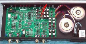
xenithon said:I unfortunately did not take a photo of the entire PCB, and the DAC is with my technician at the moment. I found a low-res image in a review and have attached an image with lines pointing to where these are located. There are three in a row (~3.3V, ~5V, ~9V). Looks like the path is from transformers to PCB through some caps and then to these, so perhaps they are indeed voltage stabilizers.
My work is in electronics and that makes recogising certain circuits a little easier. In your picture from right to left (top transfo): transfo, rectifier, smoothing caps, stabilisers, caps, circuits to be fed.
Hmmm, one thing I recall the technician saying (working from memory here) when he first look at the PCB and checked with the voltmeter, is that I believe there is a single resistor on the PCB which is, what he called, a "common ground" across all the RCA jack (there are 4 in total - 2 digital RCA inputs, and the 2 analog outputs).
Yes, that sounds logical. In most designs everything shares the same ground (common). But they are kept separate except at the connection point.
But that still means that a faulty power supply of one channel will have no effect on the other.
Will do, thanks. But are you refering to the 3 stabilizers (2 of which have the ripple) or components nearer the analog output stage?
I'm referring to the stabilisers.
xenithon said:It was a demo unit from an official distributor in the US (I am in South Africa). I have been in contact with the distributor and he is refusing to accept a return.
This shouldn't be too difficult for a competent tech to fix, it's just a bit of PSU ripple probably caused by defective components rather than a design flaw.
This would be an open-and-shut case under UK consumer protection law, demo does not mean unserviceable and the unit is obviously not of merchantable quality. They took on the modification request, and they should guarantee their work. The device was obviously not tested after modification, what kind of procedures do they have?
Best I can suggest is that you threaten the distributor with publicising their name and contact the manufacturer and get them to put pressure on the distributor, they're probably more concerned about the good name of their product than the distributor. Rant a bit, you've got reason to.
Worst case, you can probably get somebody local to fix it and the components won't cost much, in which case post the manufacturer and distributor names in this thread, ...it's not much but it's something.
w
wakibaki said:This shouldn't be too difficult for a competent tech to fix, it's just a bit of PSU ripple probably caused by defective components rather than a design flaw.
Agreed.
This would be an open-and-shut case under UK consumer protection law, demo does not mean unserviceable and the unit is obviously not of merchantable quality. They took on the modification request, and they should guarantee their work. The device was obviously not tested after modification, what kind of procedures do they have?
If I understand correctly, it was the US distributor that did the modification, not the SA distributor. If so, the US distributor would be responsible.
Let the technician measure the input voltages of the stabilisers with the scope and compare them to the R channel. I bet there's a significant difference.
In the power supply section there are just those three stabilizers, which I assume are common to the power supply. That is, there aren't L/R paths for these are there? Apologies for the newbie questions; I have very limited technical/electrical knowledge so want to make sure I ask the technician the right questions
This shouldn't be too difficult for a competent tech to fix, it's just a bit of PSU ripple probably caused by defective components rather than a design flaw
I am hoping so too. Would you think that the problem is with the stabilizers themselves or the rectifiers/smoothing caps which come before them?
The device was obviously not tested after modification, what kind of procedures do they have?
I have checked this with him in a number of emails and they maintain that they did test it. What was odd was that when I tested it briefly (20-30 seconds; did not want any longer due to safety concerns of an unearthed component) a few nights ago with an unearthed cable - it seemed not to exhibit the noise. Last night when I tested with both an earthed and unearthed power cable again, the noise exhibited with both. The only thing I can think of is that when they tested it, it was brief too and there was no issue?
. Worst case, you can probably get somebody local to fix it and the components won't cost much
That is the hope, yes. I am waiting for the schematic as the technician (understandably) does not want to start tinkering or making any changes at all without knowing what is actually meant to be happening on the PCB, especially the power supply section. I have already been in touch with the manufacturer for assistance.
If I understand correctly, it was the US distributor that did the modification, not the SA distributor. If so, the US distributor would be responsible.
Correct. In fact, there is no distributor here which is why I imported (I would always opt for a local channel if possible). The North Star site has a company listed but they stopped bringing in North Star almost 2 years ago.
xenithon said:In the power supply section there are just those three stabilizers, which I assume are common to the power supply. That is, there aren't L/R paths for these are there? Apologies for the newbie questions; I have very limited technical/electrical knowledge so want to make sure I ask the technician the right questions
It's quite simple. If both channels share the same power supply, then both channels would suffer from ripple coming from that supply. Since the R channel is not affected, it can only mean that it has its own power supply. Two toroids instead of one IMO is a giveaway (at least, that's what it looks like). The section in the attachment may also be some power supply circuits.
My μΩ DAC1 has three transformers, one for the digital circuits and two for the analogue circuits. One is for the L and the other for the R (I measured slight differences in the voltages, so I'm pretty sure they're separate).
I am hoping so too. Would you think that the problem is with the stabilizers themselves or the rectifiers/smoothing caps which come before them?
Stabilsers are pretty solid stuff. I'm not saying that they can't fail because they can, but they're not the usually cause of power supply problems. I have tested thousands of pcbs with stabilisers on them and I seem to remember only one failure of a stabilser!
But these were new products coming right off the assembly line.
I have checked this with him in a number of emails and they maintain that they did test it. What was odd was that when I tested it briefly (20-30 seconds; did not want any longer due to safety concerns of an unearthed component) a few nights ago with an unearthed cable - it seemed not to exhibit the noise.
Not earthing will only be dangerous when there is a serious fault that causes the case to have the same voltage as the mains. When the device is not faulty, there is no immediate danger in not earthing it. But in normal use, yes, you should earth it.
Last night when I tested with both an earthed and unearthed power cable again, the noise exhibited with both. The only thing I can think of is that when they tested it, it was brief too and there was no issue?
That's the problem with intermittent failures. This kind of failure is the most difficult for a technician to find, if it happens at all on the test bench.
That is the hope, yes. I am waiting for the schematic as the technician (understandably) does not want to start tinkering or making any changes at all without knowing what is actually meant to be happening on the PCB, especially the power supply section. I have already been in touch with the manufacturer for assistance.
It may be worth taking a closer look at the pcb (take it out to have a look at the solder side too). Maybe the US distributor left some debris that shorts intermittently. It happened to me a few times...
Attachments
Yeah, I found a picture on TNT audio, it seems to have completely symmetrical R & L supplies. It COULD be intermittent, a dry joint on one of those big caps on the 9V LH supply would probably do the trick. It could be as simple a fix as reheating the solder joints on it. Not a big risk even for a novice...
w
Oh, if we can speculate this far, sight unseen, your technician should have considered some of this. An LV PSU is something he should see every day. If he can't manage thought one, a schematic isn't going to help much.
w
Oh, if we can speculate this far, sight unseen, your technician should have considered some of this. An LV PSU is something he should see every day. If he can't manage thought one, a schematic isn't going to help much.
Hi guys. Thanks so much for the assistance thus far. I could not find any debris on the PCB. Would dry solder be visible at all?
I have some more photos which I uploaded to a hosting site (as they are larger than the size limit here).
The first one is an overview of what looks to be the power supply section. At the top left (very blurred in this photo) it says "ANALOG SUPPLY" and at the bottom right it says "DIGITAL SUPPLY". I am not sure if that "DIGITAL SUPPLY" section is the area which continues to the right in the photo. Also, you will notice that the three stabilizers are marked (top to bottom) IC2, IC3, and IC12.
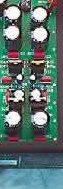
The second image is of what looks to be the "ANALOG SUPPLY".
The third image is of what looks to be labeled the "DIGITAL SUPPLY".
wakibaki - I understand you sentiment, and he does is very experienced in the field. He just wants to proceed with caution and rather have the schematic on hand than work based on assumption and speculation etc.
I have some more photos which I uploaded to a hosting site (as they are larger than the size limit here).
The first one is an overview of what looks to be the power supply section. At the top left (very blurred in this photo) it says "ANALOG SUPPLY" and at the bottom right it says "DIGITAL SUPPLY". I am not sure if that "DIGITAL SUPPLY" section is the area which continues to the right in the photo. Also, you will notice that the three stabilizers are marked (top to bottom) IC2, IC3, and IC12.
An externally hosted image should be here but it was not working when we last tested it.
The second image is of what looks to be the "ANALOG SUPPLY".
An externally hosted image should be here but it was not working when we last tested it.
The third image is of what looks to be labeled the "DIGITAL SUPPLY".
An externally hosted image should be here but it was not working when we last tested it.
wakibaki - I understand you sentiment, and he does is very experienced in the field. He just wants to proceed with caution and rather have the schematic on hand than work based on assumption and speculation etc.
Nice looking layout. The silk screen (= white printing) on the top also clearly defines the different functions. They even let the DAC straddle the line because it has both digital and analogue sections!
The only violation I've seen so far is the that the colours of the toroids' wiring don't match the description, which they probably did on purpose to avoid a twist in the wires (as these are symmetrical, that is no problem).
The idea I had of one toroid per channel was wrong. One toroid has 9-0-9 and the other one 18-0-18 written near the connection on the pcb. Also, only two wires from one toroid seem to be used for the digital power supply, all the others are located on the analogue part of the power supply.
My guess: the 18-0-18 toroid is used for a symmetrical power supply for the analogue output section. One part of the other toroid is used for a lower analogue voltage. The digital part probably needs +5V and +3.3V which are fed by the other winding.
I think there is more stabilising going on further on in the digital and analogue power supplies as I see some more TO-220 (name of that particular shape) ICs to the right.
Now that I've had a closer look at the layout, I'm not so sure anymore that L and R channels have completely separate (apart from the common GND) power supplies. So, waiting for the schematic is probably not a bad thing to do. Without it one can only get so far...
In the meantime it would be helpful if you could post what the types of all these TO-220 ICs are. I'm guessing there's LM317/337 (adjustable) and 78xx/79xx-series (fixed, e.g. a 7805 would be +5V fixed, a 7912 -12V, etc), but other types may also be used.
Nice looking layout. The silk screen (= white printing) on the top also clearly defines the different functions. They even let the DAC straddle the line because it has both digital and analogue sections!
Yes it is very neatly laid out and labelled. Below is a photo of the entire PCB which may give a better "big picture" view of what may be happening, where the power is going, and if/where it splits between L and R output. It shows the neat delineation between the "analog supply", "digital supply", "analog output", "digital input" sections etc.
An externally hosted image should be here but it was not working when we last tested it.
I think there is more stabilising going on further on in the digital and analogue power supplies as I see some more TO-220 (name of that particular shape) ICs to the right.
Does the above "big picture" photo reveal anything perhaps?
Without it one can only get so far...
Yes, the technician said he can start tinkering but would rather the schematic at hand for effective troubleshooting. By the way, I also have a close-up photo of just the analog output section, in case it helps.
An externally hosted image should be here but it was not working when we last tested it.
In the meantime it would be helpful if you could post what the types of all these TO-220 ICs are. I'm guessing there's LM317/337 (adjustable) and 78xx/79xx-series (fixed, e.g. a 7805 would be +5V fixed, a 7912 -12V, etc), but other types may also be used.
This is where my limited knowledge really starts to show
. Which components are you refering to? And would you need the white writing that is printed on those components?Cheers
X
xenithon said:
Yes it is very neatly laid out and labelled. Below is a photo of the entire PCB which may give a better "big picture" view of what may be happening, where the power is going, and if/where it splits between L and R output. It shows the neat delineation between the "analog supply", "digital supply", "analog output", "digital input" sections etc.
Does the above "big picture" photo reveal anything perhaps?
The power supply traces seem to be hidden from view (they're probably on the solder side of the pcb). So I can't really tell from the picture if they are separate.
Yes, the technician said he can start tinkering but would rather the schematic at hand for effective troubleshooting. By the way, I also have a close-up photo of just the analog output section, in case it helps.
Other than some flux residue from solder wire (the brownish stuff) between the pins of the two transistors in the lower left corner (L channel, BTW), I don't see anything out of the ordinary.
This may just be the result of touching up at the factory or a repair at a later stage...
This is where my limited knowledge really starts to show
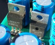
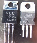
Let me help you. Usually three things are printed on the component: the brand, the type and a batch code. I'm only interested in the type (several brands produce the same type of very common components).
In the attachment you can see an LM337 and an LM317, the writing below the type is not of intrest to me. You will find similar printing on the case of other types.
It would be useful to have the reference designator (i.e. IC1, IC12, etc.) that is printed on the PCB next to the component too (e.g. IC53 = LM317).
Attachments
- Status
- This old topic is closed. If you want to reopen this topic, contact a moderator using the "Report Post" button.
- Home
- Source & Line
- Digital Line Level
- Assistance in diagnosing Hum/Buzz/Noise