Hi Folks,
many has been published on the subject in litterature. There are people who 'hate' IV's-with-op-amps as Mr. Hawksford in his article:
http://www.essex.ac.uk/dces/researc...Current steering transimpedance amplifier.pdf
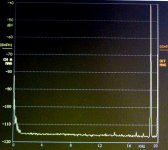
When I measure my IV with three times OPA314 onder the same conditions as Hawksford simulated in fig. 3-9a on page 17, I get the attached picture. Moreover the IV sounds terrific. What should be wrong with (the right) op amps in an IV?
My IV looks like:
http://www.by-rutgers.nl/PDFiles/CD_eind.pdf
on the last page. Sorry that the text is in Dutch....
This IV follows a selected PCM63P__K with 8 times oversampling.
many has been published on the subject in litterature. There are people who 'hate' IV's-with-op-amps as Mr. Hawksford in his article:
http://www.essex.ac.uk/dces/researc...Current steering transimpedance amplifier.pdf
When I measure my IV with three times OPA314 onder the same conditions as Hawksford simulated in fig. 3-9a on page 17, I get the attached picture. Moreover the IV sounds terrific. What should be wrong with (the right) op amps in an IV?
My IV looks like:
http://www.by-rutgers.nl/PDFiles/CD_eind.pdf
on the last page. Sorry that the text is in Dutch....
This IV follows a selected PCM63P__K with 8 times oversampling.
Attachments
The fast and steep change of the DAC output current from one sample to the next can overload the input of the opamp.
Correct me if I am wrong but you eliminated the output coupling cap by introducing another cap and an opamp in the servo loop. You wrote that this opamp has to be 'mooi klinken' so it surely affects the final quality. Easier were to put a CCS at the output of the DAC so that no DC current flows through the feedback resistor and the output of the first opamp remains at 0V.
I am also questioning the necessity of any low-pass filtering, but this is just a personal (purist) preference, and it can be disputed from engineering point of view. For me it sounds better without.
I tried several opamps in my I/V (1.5k feedback, with output coupling capacitor): SE5534, OPA134, THS4031, now I settled at OPA627. There are bigger difference between them than between no output capacitor and a (reasonable quality) output capacitor. Still, opamp I/V is a compromise for me, until my tube I/V is ready.
I think one of the problems is that at high frequencies, the opamp needs to supply a jump in current to charge the feedback cap in short time. Have you tried a first I/V stgae with very little gain, say 100 ohms instead of 2.2k feedback R, followed by a low noise gain stage.
I would expect the input R to be much flatter then.
The input cap doesn't do too much as it is in parallel with the virtual earth.
Jan Didden
I would expect the input R to be much flatter then.
The input cap doesn't do too much as it is in parallel with the virtual earth.
Jan Didden
PA0SU,
I think the valid figure to compare with your [really beautiful] measured output, is not the aforementioned fig 3-9a, with 192KHz Fs, but the fig 3-10a, with Fs 384 [in your case, 352.8 KHz]. And looking at the figures in this way, they are in perfect accordance, the article and your test. You have a noise floor slightly above -120dB, the spurious products in the simulation from the article are all below -120dB!
Ciao, George
Janneman, Őshifis!
I think the real question that PA0SU is posing here is not "what is wrong with my opamp IV" but rather "explain to me why is it that my opamp IV mesasures so well while it should not, according to the simulations of Hawksford?"
To understand this well, one should read carefully the cited article.
My answer to PA0SU is in the above post.
Ciao, George
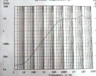
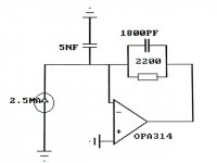
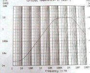
With this capacitor, the input impedance should look like in the attachement. The input impedance never exceeds 10 ohm any more.
Is this low enough?
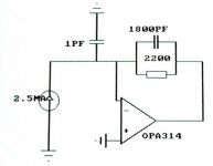
Well, the output current of the PCM63 is 2 mA with a slope of 200 ns, so that the voltage over the input never exceeds 20 mV.
The amplification of the OPA314 is 1 at 8 MHz (GB = 1 at 8 MHz) or higher. The only question is: do we get slew rate distortion at 3.528 MHz which is 8 x fs? The total amplification is also 1 there (following my simulation), but it could be that one of the first stages in the op amp would clipp so that slew rate distortion comes in sight.
I gues not because of the excellent results of the measurements. There is no any noticable intermodulation when two signals of -6.4 dB of resp. 19 and 20 kHz has been input....
Could anybody reassure my mind at rest?
Is this low enough?
Well, the output current of the PCM63 is 2 mA with a slope of 200 ns, so that the voltage over the input never exceeds 20 mV.
The amplification of the OPA314 is 1 at 8 MHz (GB = 1 at 8 MHz) or higher. The only question is: do we get slew rate distortion at 3.528 MHz which is 8 x fs? The total amplification is also 1 there (following my simulation), but it could be that one of the first stages in the op amp would clipp so that slew rate distortion comes in sight.
I gues not because of the excellent results of the measurements. There is no any noticable intermodulation when two signals of -6.4 dB of resp. 19 and 20 kHz has been input....
Could anybody reassure my mind at rest?
Attachments
Joseph K said:PA0SU,
I think the valid figure to compare with your [really beautiful] measured output, is not the aforementioned fig 3-9a, with 192KHz Fs, but the fig 3-10a, with Fs 384 [in your case, 352.8 KHz].Ciao, George
You are right, absolutely. Thank you!
Why is Hawksford so upset about op amps here? Do you have any idea?
PA0SU,
Maybe if you could repeat your test with 44.1KHz sample rate, than the slew rate limited nature of the OP134 would come in the picture and you would get the spurs in accordance with fig 3-8a [that is, around -70dB?]
Such a test would help to understand if the HAwksford article gets it right or not..? Even if in everyday use, the presence of oversampling/filtering makes the question moot?
Ciao, George
OK, but I thought that that rising Zout was upsetting as well.
If you have the time and inclination, could you graph the output current of the opamp with/without the input capacitor? I assume it would have a shape similar to the Zout curve. I'm curious about the magnitude.
Jan Didden
If you have the time and inclination, could you graph the output current of the opamp with/without the input capacitor? I assume it would have a shape similar to the Zout curve. I'm curious about the magnitude.
Jan Didden
I was not ready with my last posting.... please look there....oshifis said:The fast and steep change of the DAC output current from one sample to the next can overload the input of the opamp.
If you interconnect pin 5 and 6 on the PCM63, there is no DC in the feed back resistor. There is onother reason to use two op amps there. Without the lower one, the op amp would 'see' the impedance of the T-filter which reduces the slope at -100 dB and further.Correct me if I am wrong but you eliminated the output coupling cap by introducing another cap and an opamp in the servo loop. You wrote that this opamp has to be 'mooi klinken' so it surely affects the final quality. Easier were to put a CCS at the output of the DAC so that no DC current flows through the feedback resistor and the output of the first opamp remains at 0V.
this is not the subject of my anxiety. If you have a decent filter at the input of your power amp, you could leave it out, but the interconnect could give problems in case..I am also questioning the necessity of any low-pass filtering, but this is just a personal (purist) preference, and it can be disputed from engineering point of view. For me it sounds better without.
In the TentDAC and in the DIY-player is an tube IV. It does not convince me. They sound good but the effort is to big and my op amp IV still sounds better....I tried several opamps in my I/V (1.5k feedback, with output coupling capacitor): SE5534, OPA134, THS4031, now I settled at OPA627. There are bigger difference between them than between no output capacitor and a (reasonable quality) output capacitor. Still, opamp I/V is a compromise for me, until my tube I/V is ready.
No!.janneman said:Have you tried a first I/V stgae with very little gain, say 100 ohms instead of 2.2k feedback R, followed by a low noise gain stage.
I would expect the input R to be much flatter then.
 .. the input impedance elevates at higher frequencies because the decreasing gain. Look at my simultions! I do not post them for nothingness.
That virtual earth is 10 oms and more at high frequencies so the 5 nF starts its function at about 3.5 MHz....The input cap doesn't do too much as it is in parallel with the virtual earth.
PA0SU said:No!.
I know. I didn't mean to appear not to read your posts...
I thought that with the high (relatively) gain and at higher freqs, there might be some current limiting or slew rate limiting mechanism in the output stage, that would disappear with lower gains, and flatten the Zout curve.
Jan Didden
janneman said:OK, but I thought that that rising Zout was upsetting as well.
If you have the time and inclination, could you graph the output current of the opamp with/without the input capacitor? I assume it would have a shape similar to the Zout curve. I'm curious about the magnitude.
Jan Didden
The output impedance sticks to 10 ohm, equal to the input impedance as long as the amplification of the op amp is large. It starts to fall at 1 MHz and drops to some 500 mOhm at 100 MHz independent of the 5 nF.....
Re: slew rate
Yes, thanks.
Jan Didden
PA0SU said:The OPA134 has a slew rate of 20V/us. This is per 200 ns (= the output of the PCM63) 4 volt.
I calculated 2 mA over 10 ohm = 20 mV, so the op amp could follow the slope without slew rate distortion.
Holds this argumentation?
Yes, thanks.
Jan Didden
PA0SU,
Hm, I was asking because in the hawksford model 1nF of Cfeedback is also included, with 1mA Dac output current, and 50V/usec slew rate for the opamp. Which is more than twice the 20V/usec for the OPA134.
And he got well visible spuries at 44.1KHz.. A test would well respond to any doubt here..
Given that Tentlabs offers that NOS filter replacement unit developed by Peter Beyer, so it should be a no pain quick test.. and also interesting for the possible users.
Ciao, George
Again, uhm, let's try to re-calculate the slew rate requisites for the OPA:
The maximum swing Ipp for the PCM63 is 4mA. That is converted by the 2.2Kohm in your converter to 8.8Vpp max. - on the OUTPUT. That is, this is the step which should be re-created by the opamp on it's output.
Slew rate is always an output parameter..
Now this is extreme, but it's how it looks your 20KHz +19KHz test signal without OS!
And this should happen in 200nS in a worst case situation. That is ~45V/usec, IF that 200nsec settling time is really 200nsec and not shorter in the reality - should look at it..
Ciao, George
- Status
- This old topic is closed. If you want to reopen this topic, contact a moderator using the "Report Post" button.
- Home
- Source & Line
- Digital Line Level
- IV-convertor with op amps....