So... I'm not very good at either electronics- or PCB design, but I do a little diy on a very amateur level. Self taught.
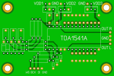
To avoid using a breadboard I thought I could make a simple PCB for myself. It's for a TDA1541A NOS dac. The schematic is the standard one with 100nF decoupling and 470pF for the oscillator. Regs are meant to be shunt, so there's no need for caps on input or output. The cirquit on the left is something proposed in another thread here on diyaudio, for slowing down the clock signal. Silk screen is not important, as I won't be using it anyway.
The pic shows a photoview from top, with the dark traces x-rayed through from the bottom layer. The light green is the ground plane on top layer.
I was looking for comments and suggestions for improving the PCB.
