I tried no_bandwidth setting too, with Buffalo II and Ian’s FIFO+si570 reclock board and SDtrans.
Ian’s si570 board allows me changing mclk frequency easily and that was very helpful.
44,1k wav with 11.2896Mhz MCLK = 95sec steady lock period, then dropped lock and relock quickly
88.2k wav with 22.5792Mhz MCLK = roughly 48sec.
96k wav with 24.576Mhz MCLK = roughly 45sec.
Same result with the others.
When playing 44.1k wav with higher MCLK frequencies, No bandwidth is completely useless,
but I repeated trying relock manually with patience, sometimes suddenly succeeded to lock in very short period. In this case, DAC loose lock after several seconds and seems never re-lock again automatically
Hi, wktk_smile,
Thank you very much for your report!
Do you perceive a better spacial focusing within the 95 seconds?
Bunpei
The improvement in SQ is not so audible for me.
Sometimes I feel slightly better focus, sometimes I feel it's leaner.
And It seems the audibility of these characteristics is varied with genre of music or quality of recordings.
It's just a kind of funny experiment.
Tackbon in Japan tried a synchronous master clocking of 1.4112 MHz on 44.1 kHz/16 bit PCM source under OSF=OFF condition. The master clock was prepared by dividing a BCLK.
He happened to get a lock only on DPLL Bandwidth, Best default or High. He describes the obtained sound quality, "like an AM radio sound".
imitating true 9-bit differential mode
test was done by sdtrans - Ian's FIFO + si570board - BuffaloII(ES9018) + Arduino(Hifiduino code, modded a bit)
First of all, As far as I know, true differential mode + 9-bit quantizer register
settings only result in distorted sound.
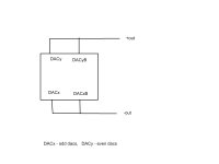
Output pins are rearranged as shown in attached drawing(and of course each dac polarity must be re-programed)
register settings are :
- mono mode
- Pseudo differential mode
- 9-bit quantizer
results:
Positive output + DC block cap connected to SE input of the amplifier
- Clean audio playback, not distorted like true-differential register setting under 9bit quantizer mode.
Positive and Negative output followed by line transformer (for BAL-SE conversion)
- Clean audio playback.
Positive and Inverted Negative output (now same polarity with positive output), followed by line transformer
- Successfully cancelled.
Sonice difference, 9-bit vs 8-bit true differential (only register settings were changed)
Under 9-bit quantizer mode, the sound is less bold, and attacks are more solid, noises contained in recordings are more audible. Although those difference are very small amount and It required me repetitive comparison over
and over.
test was done by sdtrans - Ian's FIFO + si570board - BuffaloII(ES9018) + Arduino(Hifiduino code, modded a bit)
First of all, As far as I know, true differential mode + 9-bit quantizer register
settings only result in distorted sound.
Output pins are rearranged as shown in attached drawing(and of course each dac polarity must be re-programed)
register settings are :
- mono mode
- Pseudo differential mode
- 9-bit quantizer
results:
Positive output + DC block cap connected to SE input of the amplifier
- Clean audio playback, not distorted like true-differential register setting under 9bit quantizer mode.
Positive and Negative output followed by line transformer (for BAL-SE conversion)
- Clean audio playback.
Positive and Inverted Negative output (now same polarity with positive output), followed by line transformer
- Successfully cancelled.
Sonice difference, 9-bit vs 8-bit true differential (only register settings were changed)
Under 9-bit quantizer mode, the sound is less bold, and attacks are more solid, noises contained in recordings are more audible. Although those difference are very small amount and It required me repetitive comparison over
and over.
Attachments
to glt
From Dustin's post#35 in this thread.
the DAC becomes a 7 bit quantizer (thus reducing out of band noise) and I simple divinded up the 7 bit number coming from the qunatizer into 2 6 bit numbers and inverted 1 of them. Then I send off these new 2 6 bit numbers which the differnce is mathematically identical to the origanal 7 bit number from the quantizer and shipped them off to the analog section.
I think he meant 7-bit pseudo differential mode there.
9bit number can be split to two 8bit ones, only under pseudo differential register setting. Let's call them as half-9bitA and half-9bitB.
Usually one of them are just inverted (and assigned to DACXB), thus we can get complete audio output only after Bal-Se conversion.
If same polar these half-9bitA and half-9bitB connected in paralell is identical to complete 9-bit quantizer mode output, we can get two 9-bit SE output
from one IC without BAL-SE conversion circuit.
Then Additional polarity programming and Mono mode setting should enable us to "imitate" true differential mode.
I'd like to discuss some details of quantizer bit length expansion option on ES9018.
The basic hardware design of one Analog DAC section of ES9018 is of 6 bit.
A "qunantizer bit length expansion" technique is a combination of multiple 6 bit DAC sections to obtain higher resolutions equivalent to those of 7, 8 or 9 bit DAC.
Let's think of a definite case.
A six bit DAC should have 64 levels including 0.
6 bit: values ... 63 - 0
A nine bit DAC should have 512 levels including 0.
9 bit: values ... 511 - 0
In the case we need to yield 9 bit levels by a combination of eight 6 bit values:
Target value 511
DAC1 - 63
DAC2 - 63
DAC3 - 63
DAC4 - 63
DAC5 - 63
DAC6 - 63
DAC7 - 63
DAC8 - 63
------------------------
Total 504
Alas, the sum of 8 individual DAC output is less than the ideal target value 511! How can we compensate the shortage?
Hi, Raymond, do you have any idea?
I'd like to discuss some details of quantizer bit length expansion option on ES9018.
The basic hardware design of one Analog DAC section of ES9018 is of 6 bit.
A "qunantizer bit length expansion" technique is a combination of multiple 6 bit DAC sections to obtain higher resolutions equivalent to those of 7, 8 or 9 bit DAC.
Let's think of a definite case.
A six bit DAC should have 64 levels including 0.
6 bit: values ... 63 - 0
A nine bit DAC should have 512 levels including 0.
9 bit: values ... 511 - 0
In the case we need to yield 9 bit levels by a combination of eight 6 bit values:
Target value 511
DAC1 - 63
DAC2 - 63
DAC3 - 63
DAC4 - 63
DAC5 - 63
DAC6 - 63
DAC7 - 63
DAC8 - 63
------------------------
Total 504
Alas, the sum of 8 individual DAC output is less than the ideal target value 511! How can we compensate the shortage?
Hi, Raymond, do you have any idea?
0 is a value so you get the 512.
In 9 bit true mode it is actually 1024 levels as each phase have 512...
If you read what Dustin have written previously in this thread you will find that there are not any 6 bit DAC engines at all...
It is only a default of 6 bit data that are sent to the DAC section...
Last edited:
Hi Calvin,
Im not 100% sure what type of information you are after, but I can assure you the numbers posted on the ESS sites are true. The third party measurement was done by Steve Peterson of ATECS. I think you will find he would be a reliable source.
ATECS - Audio Test Engineering Consulting Services
Since the numbers were posted in the datasheets, we have actually made better measurements, but have chosen not to bother updateing the datasheets for confusion. The AD797 has consistantly provided the best numbers getting -135dB of DNR (A-weighting) and can do -120dB of THD+N unweighted across from 20 to 20k. We have shown other OPAMPs can do >118 THD+N at 1kHz, which is impressive, but, try measure at 5k and 7k. Thats were almost every other device tested showed "issues" dropping into the -110dB THD+N or lower. The DAC is sensitive to the power supply, but this is acutally on purpose, It would have been very tough to generate a analog reference that can achieve -135dB A-weighted 20-20k on the chip that has 1024 DAC's (64 per pin, 16 pins).
As for the sound of the DAC, it is greatly influenced by the parts connected to it. I believe this is where audio companies can come in and use their knowledge and expertise to have some product differentiation.
For the output stage:
I dont think we ever claimed a current source, but rather a "current mode". The current mode is simply when the current going in and out the pin of the chip is sensed. This mode has the benefit of cancelling 2nd and 3rd harmonics of some of the internal ananlog circuitry. The "voltage mode" is when the pin of the chip has a voltage on it that is being sensed. While this has the 2nd and 3rd hormics (at the -100dB level or so), some people have even claimed this mode is more "tube-like" Its all personal prefference.
I hope this helps out a little.
Thanks
Dustin
Bunpei, to save you for the searching I quoted the post (1532).
It is soon three years ago since I added this info to my equations..
There are 1024 1 bit DACs inside that have a logically default configuration of 64 per (DAC output) pin, but can be re-configured as you like - so it is possible to partition and route and manipulate data nearly as you wish.. Go figure..
My IR remote control system have implemented the possibility to configure over 16 million combinations (register settings) and have been the ultimate tool to explore the chip..
My current DAC revision utilizes all 1024 levels for one audio channel - so two channels are 1024 levels pr. channel as I use on DAC chip pr. channel..
Last edited:
There are 1024 1 bit DACs inside that have a logically default configuration of 64 per (DAC output) pin, but can be re-configured as you like - so it is possible to partition and route and manipulate data nearly as you wish.. Go figure..
My current DAC revision utilizes all 1024 levels for one audio channel - so two channels are 1024 levels pr. channel as I use on DAC chip pr. channel..
To me It sounds more like 10-bit single ended or 10-bit pseudo differential
- I have no idea It could be possible or not - rather than 9-bit true differential.
To me It sounds more like 10-bit single ended or 10-bit pseudo differential
- I have no idea It could be possible or not - rather than 9-bit true differential.
I am finished with the ES9018 experiments now, but if not I would have tried to build a 4 chip system running in discrete 10 bit true differential mode.
With the 9 bit true differential version I have the reference I needed to benchmark the discrete DAC I have in works.
One bit resolution is lost to remove the #noise...
With the #noise in action it sounds like a bad AM radio in OSF bypass mode...
Last edited:
Hi, Raymond,
Thank you very much for showing me Dustin's post in the past.
However, ...
If you read what Dustin has written previously in this thread you will find that there are not any "arbitrary configurations" of 1 bit DACs at all ...
Those 64 x 1 bit DAC are apparently bound to one output pin. You can't assign one of them to another pin. So, we must handle them as a group of 64 pieces.
Wktk_smile reported that no 9 bit true differential mode gave normal sounds while you say 9 bit true differential is established. I was much confused with this. I'm afraid that both of you are based on different definitions of "true-differential".
Thank you very much for showing me Dustin's post in the past.
However, ...
... There are 1024 1 bit DACs inside that have a logically default configuration of 64 per (DAC output) pin, but can be re-configured as you like - so it is possible to partition and route and manipulate data nearly as you wish.. Go figure..
If you read what Dustin has written previously in this thread you will find that there are not any "arbitrary configurations" of 1 bit DACs at all ...
Those 64 x 1 bit DAC are apparently bound to one output pin. You can't assign one of them to another pin. So, we must handle them as a group of 64 pieces.
... With the 9 bit true differential version I have the reference I needed to benchmark the discrete DAC I have in works. ...
Wktk_smile reported that no 9 bit true differential mode gave normal sounds while you say 9 bit true differential is established. I was much confused with this. I'm afraid that both of you are based on different definitions of "true-differential".
Last edited:
I'm afraid that both of you are based on different definitions of "true-differential".
True differential are true differential so it is not definition but implementation that are different
A six bit DAC should have 64 levels including 0.
6 bit: values ... 63 - 0
A nine bit DAC should have 512 levels including 0.
9 bit: values ... 511 - 0
In the case we need to yield 9 bit levels by a combination of eight 6 bit values:
Target value 511
DAC1 - 63
DAC2 - 63
DAC3 - 63
DAC4 - 63
DAC5 - 63
DAC6 - 63
DAC7 - 63
DAC8 - 63
------------------------
Total 504
Alas, the sum of 8 individual DAC output is less than the ideal target value 511! How can we compensate the shortage?
Raymond's indication and explanation on Dustin's post has led me to more reasonable understanding. Thank you very much, Raymond.
I found the quantizer bit length notation is somewhat different from the conventional notation used for multi-bit DACs.
6 bit quantizer => 64 x 1 bit DACs : it can represent 65 levels including 0.
6 bit quantizer: value range [64 - 0]
9 bit quantizer => 512 x 1 bit DACs: it can represent 513 levels including 0.
9 bit quantizer: value range [512 - 0]
In the case we can yield 9 bit integer output values by a combination of eight 6 bit integer values:
Target value 512
DAC1 - 64
DAC2 - 64
DAC3 - 64
DAC4 - 64
DAC5 - 64
DAC6 - 64
DAC7 - 64
DAC8 - 64
------------------------
Total 512
Target value 0
DAC1 - 0
DAC2 - 0
DAC3 - 0
DAC4 - 0
DAC5 - 0
DAC6 - 0
DAC7 - 0
DAC8 - 0
------------------------
Total 0
Now, we have sufficient values!
Why do the Avcc buffer in ES9008's evaluation board not oscillate,
even with AD797 which is known as easily oscillate opamp and 2uF enormous capacitive load?
Try with 100nF
Why do the Avcc buffer in ES9008's evaluation board not oscillate,
even with AD797 which is known as easily oscillate opamp and 2uF enormous capacitive load?
a small capacitor of some 50-100pf in series with another resistor, together bypassing the FB resistor, increases capacitive drive ability for the AD797, plus here we are talking about low voltage and its not driving a low impedance. needs careful layout, especially at unity gain, but it works no problem.
alternatively, try lme49990
thank you roender , qusp.
I read AD797's datasheet and found a description about paralleling small C <33p with 100ohm resister.
Although there is no such C or any effective snubber but a simple voltage follower...
The AVcc buffer drives half of the current output from ES9008's analog output in the evaluation board's configuration.
The AC analog output is differential ,thus its load is always almost DC 2.112mA*8DACs= 16.896mA(=195 ohm!) and 1+1uF and offset generator.
I feel it is not so light load though it have (ideally) no voltage swing ,but does it have any influecnce for stability?
I read AD797's datasheet and found a description about paralleling small C <33p with 100ohm resister.
Although there is no such C or any effective snubber but a simple voltage follower...
Could you explain in detail?plus here we are talking about low voltage and its not driving a low impedance.
The AVcc buffer drives half of the current output from ES9008's analog output in the evaluation board's configuration.
The AC analog output is differential ,thus its load is always almost DC 2.112mA*8DACs= 16.896mA(=195 ohm!) and 1+1uF and offset generator.
I feel it is not so light load though it have (ideally) no voltage swing ,but does it have any influecnce for stability?
Attachments
Last edited:
- Home
- Source & Line
- Digital Line Level
- ESS Sabre Reference DAC (8-channel)