I'm sorry that I have not checked whether it is a FAQ or somewhere it is explained.
There are 7 power pins on ES9018 for +1.2V power;
1 VDD_L Analog Power(+1.2V) for Left channels
16 VDD_L Analog Power(+1.2V) for Left channels
20 VDD Digital Power(+1.2V) for core of chip
29 VDD Digital Power(+1.2V) for core of chip
33 VDD_R Analog Power(+1.2V) for Right channels
48 VDD_R Analog Power(+1.2V) for Right channels
61 VDD Digital Power(+1.2V) for core of chip
I understand that "Analog Power" means "related to analog DAC section" of the chip and "Digital Power" means "related to digital processing core section" and all power lines are connect to internal digital circuits.
Does any one have any clear empirical result that it's better for us to assign separate +1.2V regulators for "Analog Power" and "Digital Power" respectively?
I found acko's DAC board provides separate power input terminals.
Both Power and signals are not combined on the AKD12 board to give flexible options, especially if we not sure how the Analog/Digital sections are connected internally. If you feel there is not much to be gained from separating the supplies then simply share them accordingly. But if you look at the 9016 chip this has no AVDD (1.2V) pins, possibly generated internally or connected to chip core DVDD supply and the performance is lower. Maybe there are other factors contributing to this but I have chosen the 'safe' option.
Last edited:
Oh, no commentary replies from ready critic.
To roender & Acko,
Thank you very much for your replies.
To my regret, I can't understand why a level shifter requires an independent +1.2V.
I have no board to try separated power supplies at my hand. I wish I could try.
Bunpei
To roender & Acko,
Thank you very much for your replies.
To my regret, I can't understand why a level shifter requires an independent +1.2V.
I have no board to try separated power supplies at my hand. I wish I could try.
Bunpei
Two SDTrans users, "sky" and "tackbone" in Japan are making their efforts on establishing a stable lock with "No bandwidth" setting of DPLL bandwidth parameter under OSF=ON for 44.1 kHz/ 16 bit PCM sources.
They use a carefully prepared 11.2896 MHz synchronous master clock. Sky's assumption is "No bandwidth might be achieved easily particularly when MCLK is 4 x BCLK".
As of now, the longest period they have without any unlock event is about 90 seconds. However, they say the resultant sound in the locked state has the best focusing that they have never experienced. That is the reason why they make their efforts.
To my regret, I can't understand why a level shifter requires an independent +1.2V.
The level shifters didn't required an independent voltage source, other than the power supply for the core.
My assumption is that it was much simpler to access the shifter supply on the chip by external connection rather than internal.
It could be an assumption.... My assumption is that it was much simpler to access the shifter supply on the chip by external connection rather than internal. ...
... As of now, the longest period they have without any unlock event is about 90 seconds. ...
Totally three people in Japan tried the "No Bandwidth" experiments and all of them got the same longest periods, 96 seconds in spite that they applied such different I2S sources, SDTrans and QA-550.
Does anyone give a possible interpretation for the period?
Their common conditions are;
1. 11.2896 MHz synchronous master clock supplied to ES9018
2. I2S I/F
3. 44.1 kHz/16 bit PCM sources
4. OSF = ON, DPLL Bandwidth=No Bandwidth
Hi Bunpei,
How close to the DAC is the clock? In the particular case of SDtrans384, 11.2896Mhz is not a valid clock. So, how is MCLK supplied back to the transport?
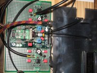
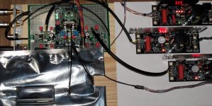
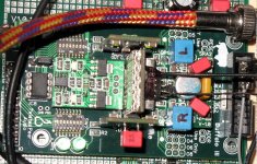
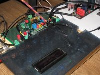
In my case, I have two CCHD957 oscilators (45.1584MHz and 49.152MHz) located very close to the DAC and the MCLK for the transport is divided by a Potato Semi D flip-flop. The DPLL bandwidth is set to "Lowest" and there are no unlocks from 44.1/16 till 192/32 PCM nor for 64 or 128DSD.
I'm not sure if BIII DAC accepts "No Bandwidth" with standard firmware in order to make experiments but will be interesting to know how is works.
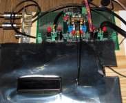
Please see the attached pictures of my setup.
Kind Regards,
Mihai
Attachments
... How close to the DAC is the clock? In the particular case of SDtrans384, 11.2896Mhz is not a valid clock. So, how is MCLK supplied back to the transport? ...
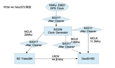
Among three, Tackbon uses SDTran384. Other two use QA-550 with NDK oscillator.
Tackbon's clock configuration is shown in his diagram.
By the way, your implementation of Crystek oscillators is really admirable! You have also prepared your own AVCC power supplies for your BIII.
Hi roender,
The BIII DAC does accept "No Bandwidth". It's the DPLL BW Default switch setting.
Best regards,
Al
In that case, I have to proudly declare that my setup is unlock free. Not a single unlock from power on till the end after almost one hour of listening.
The level shifters didn't required an independent voltage source, other than the power supply for the core.
My assumption is that it was much simpler to access the shifter supply on the chip by external connection rather than internal.
That is my understanding from ESS.
roender, nice job. Really like your setup. Just curious, can you try an spdif input with the DPLL set to "No Bandwidth" and DPLL Multiplier set to 1X to see if your setup still maintains lock? Thanks!
Al
I just powered on the DVD player and voila, no unlocks!
The DAC switches automatically from I2S to SPDIF when it sees signal on D3 which is connected via TOSLINK
Last edited:
Hi Brian,
Just to clarify. In Buffalo III, when setting the DPLL BW to Default is the "No Bandwidth" selection in Register 11 being used, and Register 25 set to "Allow all settings", or is Register 25 set to "Use the best DPLL bandwidth settings". Thanks!
Al
Just to clarify. In Buffalo III, when setting the DPLL BW to Default is the "No Bandwidth" selection in Register 11 being used, and Register 25 set to "Allow all settings", or is Register 25 set to "Use the best DPLL bandwidth settings". Thanks!
Al
Last edited:
roender, I think I misspoke. After looking at the ES9018 DS, and the Buffalo III manual in more detail, I don't think Buffalo III allows for the "No Bandwidth" setting. I think the "Default" dip switch selection sets Register 25 in the ES9018 to "Use the best DPLL bandwidth settings" which is the initial default setting.
Al
Al
roender, I think I misspoke. After looking at the ES9018 DS, and the Buffalo III manual in more detail, I don't think Buffalo III allows for the "No Bandwidth" setting. I think the "Default" dip switch selection sets Register 25 in the ES9018 to "Use the best DPLL bandwidth settings" which is the initial default setting.
Al
You are right, BIII doesn't support DPLL "No Bandwidth" setting.
What confuse me is why DPLL is up and running in sync mode?
- Home
- Source & Line
- Digital Line Level
- ESS Sabre Reference DAC (8-channel)