True and Pseudo differential mode
By using TPA Buffalo III board, we can now try one of the undocumented ES9018 register settings, Differential output mode, "True" or "Pseudo". This setting has a close relationship to Quantizer Bit Length, especially 9 bit mode.
On this topic, we can read Dustin's original post and glt's valuable report on his intensive experiments.
First, I'd like to have a clear understanding on the meaning of "True" and "Pseudo" in the differential mode and to appreciate your comments.
My basic understanding is;
1. In "True" differential mode, an normal output signal "+" appears between A_GND pin and "DACn" pin and counterpart output signal "-" appears between A_GND pin and "DACnB" pin.
2. In "Pseudo" differential mode, a single output signal appears between "DACn" pin and "DACnB" pin.
What I can't understand well is how this difference would affect the design of I/V stages, especially in terms of GND handling. In my case, as I only use transformer I/V stage or earphones and use no GND pins, no difference is recognized.
By using TPA Buffalo III board, we can now try one of the undocumented ES9018 register settings, Differential output mode, "True" or "Pseudo". This setting has a close relationship to Quantizer Bit Length, especially 9 bit mode.
On this topic, we can read Dustin's original post and glt's valuable report on his intensive experiments.
I'd like to continue the topic especially on a consideration of quantizer bit setting. I'm not sure whether the term "quantizer" is a popular technical term in the field of sigma-delta DAC or not.
My basic understanding is as follows;
1. A sigma-delta type DAC chip consists of a "modulator" and a "digital to analog" module. The first generation sigma-delta DAC used to have 1-bit digital to analog conversion hardware.
2. In the case of this modern Sabre32 architecture, the chip has a bunch of 6 bit "digital to analog" modules in a chip. The number is 8 modules ( 4 channels x 2 (+,-) ) per side and totally 16 modules.
3. When the 9 bit quantizer setting is selected, the modulator generates time series values that match 9 bit digital to analog module. However, the hardware is of only 6 bit capability. Extra 9-6=3bit ( 0 - 7 level) is processed as the simple ON/OFF of the 8 modules of which analog outputs are set to be tied together on this setting. This can be regarded as just one digital to analog module per side. On the setting, having a true differential + and - outputs is impossible and only a pseudo differential output is available.
Synchronous MCLKing scheme for ES9018
Chiaki made a set of optional boards for demonstrating "Proof of Concept" of effectiveness of synchronous MCLK feed to ES9018 DAC chip using dual oscillators.
(The smaller board at the top left in the picture below is a DAC side sub board and the larger one at the bottom right is a transport side sub board.)
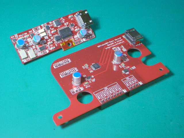
I guess the similar scheme might be realized in the next new TPA USB-I2S board.
Two oscillators, 90.3168 MHz & 98.304 MHz, are located on the DAC side sub board. The oscillators are located on the left bottom corner of the board. They are NDK (Nippon Denpa Kogyo) low phase noise LVPECL output type devices.
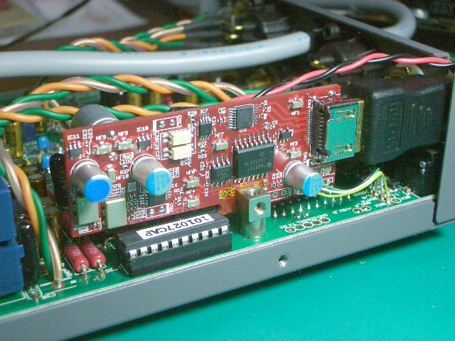
(The DAC side sub board is embedded into Japanese Fidelix CAPRICE DAC.)
One of two frequencies is to be selected depending on the sampling frequency of the source by a command sent from the transport side via I2C lines on PS-Audio standard I2S interface (I2S/LVDS & I2C on HDMI Connector & Cable).
The selected oscillator output is injected to ES9018 chip and also supplied back to the transport side via HDMI cable.
(The transport is Chiaki's SDTrans384.)
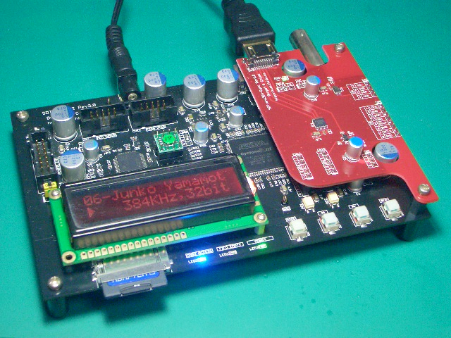
On the trasport side, the 90.3186 MHz or 98.304 MHz MCLK is divided into suitable frequencies to be used. MCLK synchronized I2S signals are send to DAC via PS-Audio standard I2S interface. The LVDS signals are isolated on the DAC side board.
As a result, under this synchronous MCLKing scheme, a stable lock state even on 384 kHz/32 bit PCM I2S input to ES9018 is obtained with register settings, OSF=ON, Jitter Eliminator=ON, DPLL Bandwidth=The Lowest.
The sonic impression of output music is excellent and Bunpei think it is demonstrating a very high potential that the ES9018 DAC chip originally possesses.
Chiaki made a set of optional boards for demonstrating "Proof of Concept" of effectiveness of synchronous MCLK feed to ES9018 DAC chip using dual oscillators.
(The smaller board at the top left in the picture below is a DAC side sub board and the larger one at the bottom right is a transport side sub board.)
I guess the similar scheme might be realized in the next new TPA USB-I2S board.
Two oscillators, 90.3168 MHz & 98.304 MHz, are located on the DAC side sub board. The oscillators are located on the left bottom corner of the board. They are NDK (Nippon Denpa Kogyo) low phase noise LVPECL output type devices.
(The DAC side sub board is embedded into Japanese Fidelix CAPRICE DAC.)
One of two frequencies is to be selected depending on the sampling frequency of the source by a command sent from the transport side via I2C lines on PS-Audio standard I2S interface (I2S/LVDS & I2C on HDMI Connector & Cable).
The selected oscillator output is injected to ES9018 chip and also supplied back to the transport side via HDMI cable.
(The transport is Chiaki's SDTrans384.)
On the trasport side, the 90.3186 MHz or 98.304 MHz MCLK is divided into suitable frequencies to be used. MCLK synchronized I2S signals are send to DAC via PS-Audio standard I2S interface. The LVDS signals are isolated on the DAC side board.
As a result, under this synchronous MCLKing scheme, a stable lock state even on 384 kHz/32 bit PCM I2S input to ES9018 is obtained with register settings, OSF=ON, Jitter Eliminator=ON, DPLL Bandwidth=The Lowest.
The sonic impression of output music is excellent and Bunpei think it is demonstrating a very high potential that the ES9018 DAC chip originally possesses.
Hello Bunpei,
and now why you don't build a new ES9018 Dac board with this solution for the SDTrans384 users?
Thankyou Bunpei for keeping us informed of the excellent progress.
I am following along this thread hoping that I can buy a SDTransport if a new version is ever produced.
Hopefully by that time I am also able to utilise this work in sync mclk 9018, it seems very promising.
Thankyou Bunpei for keeping us informed of the excellent progress.
I am following along this thread hoping that I can buy a SDTransport if a new version is ever produced.
Hopefully by that time I am also able to utilise this work in sync mclk 9018, it seems very promising.
Yes, I would be very happy indeed if given a chance to buy one of these!
Brgds
Dear digital audiophiles,
Chiaki and Bunpei were much pleased with the so many comments for the previous post.
As for the next release of SDTrans, would you read this post?
http://www.diyaudio.com/forums/digital-source/142562-microsd-memory-card-transport-project-36.html#post2787629
Chiaki and Bunpei
Chiaki and Bunpei were much pleased with the so many comments for the previous post.
As for the next release of SDTrans, would you read this post?
http://www.diyaudio.com/forums/digital-source/142562-microsd-memory-card-transport-project-36.html#post2787629
Chiaki and Bunpei
Questions on the Effect of Oversampling Filter of DSD input
According to "FUNCTIONAL BLOCK DIAGRAM" in data sheet of ES9018, DSD signal is processed in "OVERSAMPLING FILTER" block.
1. My interpretation is "no oversampling is applied to DSD data signals in this block".
Do you think it is correct?
2. In the case of I2S input, "OSF=ON or OFF" affects the effective magnitude of DPLL Bandwidth parameter. Even in the case of DSD input, does the setting "OSF=ON or OFF" affect the DPLL behavior?
As for a clock to which DPLL is subject, BCLK is said to be selected for I2S. How is for DSD? Is BCLK of DSD used for DPLL input?
DSD256 play on ES9018
Chiaki achieved a successful play of DSD256 sources on ES9018 implemented on Japanese Fidelix CAPRICE DAC. The transport used was Chiaki's SDTrans384 with Sync option. Oversampling mode was ON and DPLL Bandwidth Parameter was the "LOWEST". A synchronous master clock of 90.3168 MHz was employed.
Chiaki achieved a successful play of DSD256 sources on ES9018 implemented on Japanese Fidelix CAPRICE DAC. The transport used was Chiaki's SDTrans384 with Sync option. Oversampling mode was ON and DPLL Bandwidth Parameter was the "LOWEST". A synchronous master clock of 90.3168 MHz was employed.
Yes, its DCLK frequency is 44.1 kHz x 256 = 11.2896 MHz.
The DSD256 file was not prepared by any actual recording. I created it based on the method shown by flemming3520;
http://www.diyaudio.com/forums/exadevices/183374-exau2i-multi-channel-asynchronous-usb-i2s-interface-64.html#post2641612
The D1 and D2 signals given to ES9018 are of "DSD Normal mode".
The DSD256 file was not prepared by any actual recording. I created it based on the method shown by flemming3520;
http://www.diyaudio.com/forums/exadevices/183374-exau2i-multi-channel-asynchronous-usb-i2s-interface-64.html#post2641612
The D1 and D2 signals given to ES9018 are of "DSD Normal mode".
Hi Bunpei,
I've tried OSF bypass with 80MHz clock.
- It only works if the incoming sample is 384KHz.
- Any less and the dpll cannot lock when music is playing. It locks when there is no music playing.
- The value of the dpll is /64 (I was expecting /8)
Are there any other register to adjust when using the OSF bypass?
Thanks...
I've tried OSF bypass with 80MHz clock.
- It only works if the incoming sample is 384KHz.
- Any less and the dpll cannot lock when music is playing. It locks when there is no music playing.
- The value of the dpll is /64 (I was expecting /8)
Are there any other register to adjust when using the OSF bypass?
Hi, glt!
To my regret, I have no experience of playing 384kHz/32bit PCM on 80MHz ES9018.
The behavior seems very strange for me.
I think no other register setting is required for an OSF bypass.
Bunpei
Since I have received a few emails asking how its done here is how you get DSD from any SACD player which uses the PCM1791 like the Denon DVD-2910.
Pin 1 is DATA R
Pin 3 is DATA L
Pin 5 is the bit clock.
Then you just need GND.
Cheers!
Russ
I found this old description of how to get the DSD from a Denon DVD-2910. I just wonder if any one knows if all tone controles, incluing volume, are bypassed when selecting "source direct" in the player so the pure DSD stream is captured when picking it from the DAC.
--Per
I found Dustin's name here
DSD via USB, Toward An Open Standard | AudioStream
with his company name, "Independent".
DSD via USB, Toward An Open Standard | AudioStream
with his company name, "Independent".
Is a latch mechanism available for a read-out of DPLL_NUM?
Some ES9018 users including Hifiduino users may read 32 bit DPLL_NUM value through a series of four byte-by-byte access to register #28,#29, #30 & #31 via I2C. No latching method of the four register values is shown in ES9018 datasheet.
Does anyone know whether a latching mechanism is provided or not?
Without such a latch, we can not read an exact value of DPLL_NUM in some typical cases.
For example, in the case of applying a synchronous MCLK of 90.3168MHz, DATA_CLK of 2.8224MHz is represented as the value 0x08000000 in DPLL_NUM. However, in actual situations, it fluctuates to some extent, for example, 0x07FFFFFF – 0×08000001. While we read out register #28 – #31 values one by one, the whole value changes and each byte changes. In the worst case, an obtained value of DPLL_NUM indicates 0x08FFFFFF or 0x07000000. (We usually get a result of random shuffles.)
I found this old description of how to get the DSD from a Denon DVD-2910. I just wonder if any one knows if all tone controles, incluing volume, are bypassed when selecting "source direct" in the player so the pure DSD stream is captured when picking it from the DAC.
--Per
Denon says that in Source Direct (50kHz or 100kHz filter), the DSD stream goes unaffected into the DAC inputs. The filters are actually analog filters inside the DAC, so they won't affect the DSD stream. Selection is done with some 74LVC157 - easy to check (DSD_SEL). Same system is inside DVD-2930 too.
Attachments
Last edited:
- Home
- Source & Line
- Digital Line Level
- ESS Sabre Reference DAC (8-channel)